
Page 105 - Read Online
P. 105
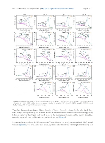
Wan et al. Microstructures 2023;3:2023014  https://dx.doi.org/10.20517/microstructures.2022.36  Page 11 of 19


                Figure 7. High-resolution XPS spectra of the corroded surface on Cr0 (A -A ), Cr0.6 (B -B ), Cr1 (C -C ), and Cr1.5 (D -D ) HEAs after
                                                                           1
                                                                 1
                                                                   4
                                                                            5
                                                                                               1
                                                                                                 5
                                                                                   1
                                                                                     5
                polarization in a 0.5 M H SO  solution at room temperature. (A -D ) Co 2p ; (A -D ) Fe 2p ; (A -D ) Mn 2p ; (A -D ) Ni 2p ; and
                                                                                                     3/2
                                                                             3/2
                                                                      2
                                                                        2
                                                                                              4
                                                                                                4
                                                                                          3/2
                                                                                 3
                                                                                    3
                                                          1
                                   4
                                2
                                                                  3/2
                                                            1
                (B -D ) Cr 2p . XPS: X-ray photoelectron spectroscopy.
                         3/2
                   5
                 5
               Therefore, the corrosion resistance follows the order of Cr1.5 > Cr0 > Cr1 > Cr0.6. On the other hand, there
               is no straight line representing the diffusion process or another capacitive semicircle corresponding pitting
               behavior present in the Nyquist plot, which is due to the simultaneous formation of the passive film at the
               corroded region when the etching solution reaches the matrix [Figure 6].
               In order to fit the results of the EIS under the OCP condition, an electrical equivalent circuit (EEC) model
               (inset in Figure 9A) was used. In the EEC model, a parallel combination of a constant phase element Q  and
                                                                                                      p