
Page 109 - Read Online
P. 109
Wan et al. Microstructures 2023;3:2023014 https://dx.doi.org/10.20517/microstructures.2022.36 Page 15 of 19
may be attributed to the dissolution rate difference of the constituent elements in these HEAs in the
corrosion environment [7,39] . The hydroxides of Cr, Mn and Fe were deposited on the surface of the HEAs by
the hydrolysis reactions at the same time, then some hydroxides formed early in the inner layer may
dehydrate to form the oxides [40,41] , such as Cr O . Therefore, the complete passive films were formed. The
3
2
major chemical reactions present in the above corrosion process are shown as follows:
n+
Anodic reaction: M → M + ne (M: constituent metal element of the HEAs)
-
Cathodic reaction: 2H + 2e → H 2
-
+
O + 2H O + 4e → 4OH -
-
2
2
Hydrolysis reaction: M + nH O → M(OH) + nH +
n+
n
2
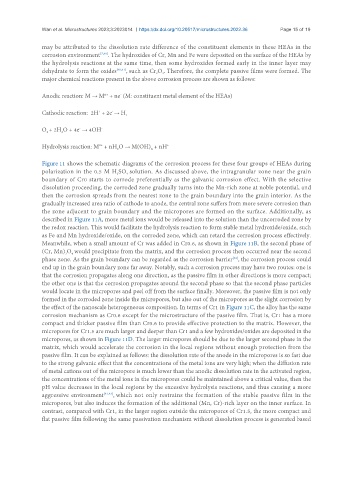
Figure 11 shows the schematic diagrams of the corrosion process for these four groups of HEAs during
polarization in the 0.5 M H SO solution. As discussed above, the intragranular zone near the grain
2
4
boundary of Cr0 starts to corrode preferentially as the galvanic corrosion effect. With the selective
dissolution proceeding, the corroded zone gradually turns into the Mn-rich zone at noble potential, and
then the corrosion spreads from the nearest zone to the grain boundary into the grain interior. As the
gradually increased area ratio of cathode to anode, the central zone suffers from more severe corrosion than
the zone adjacent to grain boundary and the micropores are formed on the surface. Additionally, as
described in Figure 11A, more metal ions would be released into the solution than the uncorroded zone by
the redox reaction. This would facilitate the hydrolysis reaction to form stable metal hydroxide/oxide, such
as Fe and Mn hydroxide/oxide, on the corroded zone, which can retard the corrosion process effectively.
Meanwhile, when a small amount of Cr was added in Cr0.6, as shown in Figure 11B, the second phase of
(Cr, Mn) O would precipitate from the matrix, and the corrosion process then occurred near the second
4
3
phase zone. As the grain boundary can be regarded as the corrosion barrier , the corrosion process could
[38]
end up in the grain boundary zone far away. Notably, such a corrosion process may have two routes: one is
that the corrosion propagates along one direction, as the passive film in other directions is more compact;
the other one is that the corrosion propagates around the second phase so that the second phase particles
would locate in the micropores and peel off from the surface finally. Moreover, the passive film is not only
formed in the corroded zone inside the micropores, but also out of the micropores as the slight corrosion by
the effect of the nanoscale heterogeneous composition. In terms of Cr1 in Figure 11C, the alloy has the same
corrosion mechanism as Cr0.6 except for the microstructure of the passive film. That is, Cr1 has a more
compact and thicker passive film than Cr0.6 to provide effective protection to the matrix. However, the
micropores for Cr1.5 are much larger and deeper than Cr1 and a few hydroxides/oxides are deposited in the
micropores, as shown in Figure 11D. The larger micropores should be due to the larger second phase in the
matrix, which would accelerate the corrosion in the local regions without enough protection from the
passive film. It can be explained as follows: the dissolution rate of the anode in the micropores is so fast due
to the strong galvanic effect that the concentrations of the metal ions are very high; when the diffusion rate
of metal cations out of the micropore is much lower than the anodic dissolution rate in the activated region,
the concentrations of the metal ions in the micropores could be maintained above a critical value, then the
pH value decreases in the local regions by the excessive hydrolysis reactions, and thus causing a more
aggressive environment [42,43] , which not only restrains the formation of the stable passive film in the
micropores, but also induces the formation of the additional (Mn, Cr)-rich layer on the inner surface. In
contrast, compared with Cr1, in the larger region outside the micropores of Cr1.5, the more compact and
flat passive film following the same passivation mechanism without dissolution process is generated based