
Page 136 - Read Online
P. 136
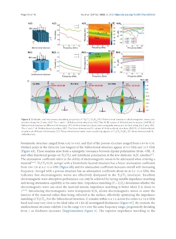
Page 10 of 16                            Xu et al. Soft Sci. 2025, 5, 43  https://dx.doi.org/10.20517/ss.2025.63


                Figure 5. Dielectric and microwave absorbing properties of Ti CT /Si N . (A1) Bidirectional structure: electromagnetic waves are
                                                           2
                                                             X
                                                                  4
                                                                3
                incident along the Z-axis; (A2) The ε’ and ε’’ of Bidirectional structure; (A3) The 3D RL values of Bidirectional structure; (A4) RL of
                Bidirectional structure at different thicknesses; (B1) Unidirectional structure: electromagnetic waves are incident along the Z-axis; (B2)
                The ε’ and ε’’ of Unidirectional structure; (B3) The three-dimensional RL values of Unidirectional structure; (B4) RL of Unidirectional
                structure at different thicknesses; (C) Three-dimensional radar wave scattering signals of Ti CT /Si N . 3D: three-dimensional; RL:
                                                                               2  X  3  4
                reflection loss.
               biomimetic structure ranged from 0.82 to 0.63, and that of the porous structure ranged from 0.69 to 0.56.
               Distinct peaks in the dielectric loss tangent of the bidirectional structure appear at 9.5 GHz and 10.5 GHz
               [Figure 6A]. These maxima arise from a synergistic resonance between dipolar polarization (from -OH, -F,
               and other functional groups on Ti CT ) and interfacial polarization at the low-dielectric Si N  interface .
                                                                                                       [61]
                                            2
                                                X
                                                                                            3
                                                                                               4
               The attenuation coefficient refers to the ability of electromagnetic waves to be attenuated when entering a
               material [62,63] . Ti CT /Si N  aerogel with a biomimetic layered structure has a better attenuation coefficient
                               X
                                     4
                                  3
                            2
               from 100-120 at 8.2-12.4 GHz [Figure 6B], and the attenuation coefficient increases overall with increasing
               frequency. Aerogel with a porous structure has an attenuation coefficient about 60 at 8.2-12.4 GHz, this
               indicates that electromagnetic waves are effectively dissipated in the Ti CT  interlayer. Excellent
                                                                                  2
                                                                                      X
               electromagnetic wave absorption performance can only be achieved by having suitable impedance matching
               and strong attenuation capability at the same time. Impedance matching (Z = Z/Z ) determines whether the
                                                                                    0
                                                                                  i
               electromagnetic wave can enter the material system; impedance matching is better when Z is closer to
               1 [64,65] . Introducing electromagnetic wave transparent Si N  allows electromagnetic waves to enter the
                                                                   4
                                                                3
               interior of the material rather than being reflected at the surface, effectively optimizing the impedance
               matching of Ti CT . For the bidirectional structure, Z remains within 0.4-1.2 across the entire 8.2-12.4 GHz
                            2
                               X
               band and stays very close to the ideal value of 1 for all investigated thicknesses [Figure 6C]. By contrast, the
               unidirectional structure exhibits Z in the range 0.8-3 over the same frequency range, progressively deviating
               from 1 as thickness increases [Supplementary Figure 9]. The superior impedance matching in the