
Page 135 - Read Online
P. 135
Xu et al. Soft Sci. 2025, 5, 43 https://dx.doi.org/10.20517/ss.2025.63 Page 9 of 16
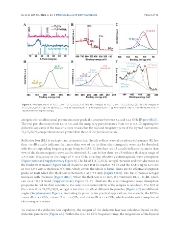
Figure 4. Microstructure of Ti CT and Ti CT /Si N . (A) The XRD images of Ti CT and Ti CT /Si N ; (B)The XPS images of
X
3
2
2
X
4
X
3
4
2
X
2
Ti CT /Si N ; (C) Si 2p XPS spectra; (D) N 1s XPS spectra; (E) C 1s XPS spectra; (F) Ti 2p XPS spectra. XRD: X-ray diffraction; XPS: X-
2
4
3
X
ray photoelectron spectroscopy.
aerogels with unidirectional porous structure gradually decrease between 8.2 and 12.4 GHz [Figure 5B(2)].
The real part decreases from 1.2 to 0.6, and the imaginary part decreases from 0.9 to 0.3. Comparing the
dielectric constants of the two structures reveals that the real and imaginary parts of the layered biomimetic
Ti CT /Si N aerogel structure are greater than those of the porous structure.
2
3
X
4
Reflection loss (RL) is an important parameter that directly reflects wave absorption performance. RL less
than -10 dB usually indicates that more than 90% of the incident electromagnetic wave can be absorbed,
with the corresponding frequency range being the EAB. RL less than -20 dB usually indicates that more than
99% of the electromagnetic wave can be absorbed. RL can be less than -10 dB within a thickness range of
4.7-8 mm, frequency in the range of 8-12.4 GHz, enabling effective electromagnetic wave absorption
[Figure 5A(3) and Supplementary Figure 6]. The RL of Ti CT /Si N aerogel increases and then decreases as
3
4
2
X
the thickness increases [Figure 5A(4)]. It can be seen that RL reaches -53 dB and the EAB is up to 4.2 GHz
at 10.8 GHz with a thickness of 5 mm, which covers the whole X-band. There are no effective absorption
peaks or EAB when the thickness is between 4 and 7.5 mm [Figure 5B(3)]. The RL of porous aerogel
increases with thickness [Figure 5B(4)]. When the thickness is 10 mm, the minimum RL is -20 dB, which
can cover the X band [Supplementary Figure 7]. To illustrate the electromagnetic wave absorption
properties in real far-field conditions, the radar cross section (RCS) of the samples is calculated. The RCS of
the 5 mm thick Ti CT /Si N aerogel is less than -20 dB at different frequencies [Figure 5C] and different
X
2
3
4
angles [Supplementary Figure 8] indicating its potential for practical applications, for example, the RCS is
-26.63 dB at 8.2 GHz, -26.40 dB at 10.3 GHz, and -26.39 dB at 12.4 GHz, which enables 99% absorption of
electromagnetic waves.
To evaluate the dielectric loss capability, the tangent of the dielectric loss was calculated based on the
dielectric parameters [Figure 6A]. Within the 8.2-12.4 GHz frequency range, the tangent loss of the layered