
Page 33 - Read Online
P. 33
Blewitt et al. Soft Sci 2024;4:13 https://dx.doi.org/10.20517/ss.2023.49 Page 15 of 26
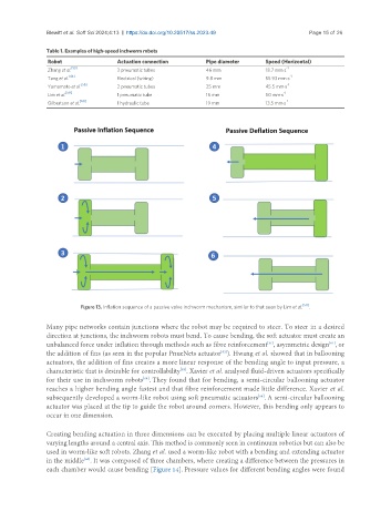
Table 1. Examples of high-speed inchworm robots
Robot Actuation connection Pipe diameter Speed (Horizontal)
Zhang et al. [55] 3 pneumatic tubes 46 mm 18.7 mm·s -1
[46] -1
Tang et al. Electrical (wiring) 9.8 mm 55.93 mm.s
[58] -1
Yamamato et al. 2 pneumatic tubes 25 mm 45.5 mm·s
[59] -1
Lim et al. 1 pneumatic tube 16 mm 50 mm·s
[60] -1
Gilbertson et al. 1 hydraulic tube 19 mm 13.5 mm·s
Figure 13. Inflation sequence of a passive valve inchworm mechanism, similar to that seen by Lim et al. [59] .
Many pipe networks contain junctions where the robot may be required to steer. To steer in a desired
direction at junctions, the inchworm robots must bend. To cause bending, the soft actuator must create an
[61]
[31]
unbalanced force under inflation through methods such as fibre reinforcement , asymmetric design , or
the addition of fins (as seen in the popular PnueNets actuator ). Hwang et al. showed that in ballooning
[62]
actuators, the addition of fins creates a more linear response of the bending angle to input pressure, a
characteristic that is desirable for controllability . Xavier et al. analysed fluid-driven actuators specifically
[63]
for their use in inchworm robots . They found that for bending, a semi-circular ballooning actuator
[64]
reaches a higher bending angle fastest and that fibre reinforcement made little difference. Xavier et al.
subsequently developed a worm-like robot using soft pneumatic actuators . A semi-circular ballooning
[64]
actuator was placed at the tip to guide the robot around corners. However, this bending only appears to
occur in one dimension.
Creating bending actuation in three dimensions can be executed by placing multiple linear actuators of
varying lengths around a central axis. This method is commonly seen in continuum robotics but can also be
used in worm-like soft robots. Zhang et al. used a worm-like robot with a bending and extending actuator
in the middle . It was composed of three chambers, where creating a difference between the pressures in
[65]
each chamber would cause bending [Figure 14]. Pressure values for different bending angles were found