
Page 28 - Read Online
P. 28
Page 10 of 26 Blewitt et al. Soft Sci 2024;4:13 https://dx.doi.org/10.20517/ss.2023.49
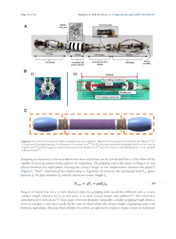
Figure 8. (A) Inchworm mechanism made using traditional rigid actuators. Reprinted with permission from Basem and Bastaki [39] ; (B)
Comparison of the initial gripping unit developed by Kusunose et al. [40] . (i) The improved mechanism integrated into the whole robot by
Hayashi et al. [41] , (ii) Both images printed with permission from Hayashi et al. [41] ; and (C) Inchworm robot developed by Li et al. reprinted
with permission [44] .
designing an inchworm robot as it determines how much load can be carried and hence if the robot will be
capable of carrying sensors/tools required for inspection. The gripping unit in the study by Fang et al. was
placed between two rigid plates limiting the contact length to the displacement between the plates
[43]
[Figure 9]. They determined the relationship in Equation (4) between the maximum load F given
[43]
max
pressure p, the pipe diameter D , and the minimum contact length L . s
p
Fang et al. found that for a 25 mm diameter pipe, the gripping units would be sufficient with a 32 mm
contact length, whereas for a 40 mm pipe, a 24 mm contact length was sufficient . The robot was
[43]
demonstrated in vertical and U-bend pipes of 90 mm diameter. Generally, a smaller gripping length allows a
robot to navigate a turn more easily. In the case of robots where the contact length of gripping units is set
between rigid plates, this may limit whether the robot can approach a bend or create a limit on minimum