
Page 27 - Read Online
P. 27
Blewitt et al. Soft Sci 2024;4:13 https://dx.doi.org/10.20517/ss.2023.49 Page 9 of 26
[34]
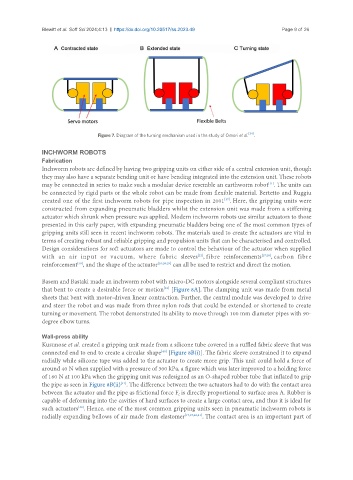
Figure 7. Diagram of the turning mechanism used in the study of Omori et al. .
INCHWORM ROBOTS
Fabrication
Inchworm robots are defined by having two gripping units on either side of a central extension unit, though
they may also have a separate bending unit or have bending integrated into the extension unit. These robots
may be connected in series to make such a modular device resemble an earthworm robot . The units can
[11]
be connected by rigid parts or the whole robot can be made from flexible material. Bertetto and Ruggiu
created one of the first inchworm robots for pipe inspection in 2001 . Here, the gripping units were
[37]
constructed from expanding pneumatic bladders whilst the extension unit was made from a stiffening
actuator which shrunk when pressure was applied. Modern inchworm robots use similar actuators to those
presented in this early paper, with expanding pneumatic bladders being one of the most common types of
gripping units still seen in recent inchworm robots. The materials used to create the actuators are vital in
terms of creating robust and reliable gripping and propulsion units that can be characterised and controlled.
Design considerations for soft actuators are made to control the behaviour of the actuator when supplied
with an air input or vacuum, where fabric sleeves , fibre reinforcements [27,28] , carbon fibre
[21]
reinforcement , and the shape of the actuator [10,26,29] can all be used to restrict and direct the motion.
[38]
Basem and Bastaki made an inchworm robot with micro-DC motors alongside several compliant structures
[39]
that bent to create a desirable force or motion [Figure 8A]. The clamping unit was made from metal
sheets that bent with motor-driven linear contraction. Further, the central module was developed to drive
and steer the robot and was made from three nylon rods that could be extended or shortened to create
turning or movement. The robot demonstrated its ability to move through 100 mm diameter pipes with 90-
degree elbow turns.
Wall-press ability
Kusunose et al. created a gripping unit made from a silicone tube covered in a ruffled fabric sleeve that was
[40]
connected end to end to create a circular shape [Figure 8B(i)]. The fabric sleeve constrained it to expand
radially while silicone tape was added to the actuator to create more grip. This unit could hold a force of
around 40 N when supplied with a pressure of 300 kPa, a figure which was later improved to a holding force
of 160 N at 100 kPa when the gripping unit was redesigned as an O-shaped rubber tube that inflated to grip
[41]
the pipe as seen in Figure 8B(ii) . The difference between the two actuators had to do with the contact area
between the actuator and the pipe as frictional force F is directly proportional to surface area A. Rubber is
f
capable of deforming into the cavities of hard surfaces to create a large contact area, and thus it is ideal for
[42]
such actuators . Hence, one of the most common gripping units seen in pneumatic inchworm robots is
radially expanding bellows of air made from elastomer [17,37,40,41] . The contact area is an important part of