
Page 25 - Read Online
P. 25
Blewitt et al. Soft Sci 2024;4:13 https://dx.doi.org/10.20517/ss.2023.49 Page 7 of 26
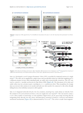
Figure 5. Comparison of the speed from a 7-unit Earthworm mechanism (A) and a 4-unit (B). Reprinted with permission from Mano
et al. [28] .
Figure 6. (A) Bi-directional sliding mechanism robot. Reprinted with permission from Yamamoto et al. [29] ; (B) Sequential actuation of
earthworm mechanism by use of a novel rotational flow control valve, reprinted with permission from Sato et al. [26] .
Sato et al. developed a novel Compact Pneumatic Valve (CPV) controlled by rotational motion of a single
motor . The valve can be supplied by a single source and periodically rotates an outlet hole supplying air to
[26]
a different actuator in turn, while simultaneously, an outlet valve is periodically rotated too. The CPV was
used to control a 7-module earthworm In-Pipe Robot (IPR) [Figure 6B]. The placement of the inlet and
outlet valves was two actuators apart, resulting in a 5-1-1 earthworm robot. This streamlines the design
since an external valve system is not needed and only one tube needs to be connected to the robot, though
tubing between the individual actuators is still required.
Sato et al. integrated solenoids directly into the actuators, meaning they could release air directly from
the actuator to the environment and hence, only one supply line was required . This was used to create a
[26]
6-unit robot capable of traversing 150 mm pipelines. Rigid valves can be quite large meaning that by
integrating them directly into the robot, miniaturisation potential is limited. A wireless and tubeless
earthworm mechanism [Figure 3D] is demonstrated by You et al. . The robot is made from magneto-
[30]