
Page 24 - Read Online
P. 24
Page 6 of 26 Blewitt et al. Soft Sci 2024;4:13 https://dx.doi.org/10.20517/ss.2023.49
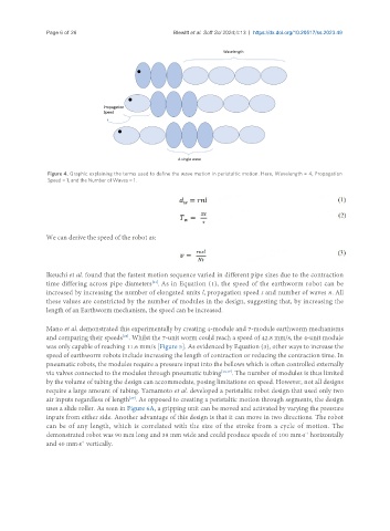
Figure 4. Graphic explaining the terms used to define the wave motion in peristaltic motion. Here, Wavelength = 4, Propagation
Speed = 1, and the Number of Waves = 1.
We can derive the speed of the robot as:
Ikeuchi et al. found that the fastest motion sequence varied in different pipe sizes due to the contraction
[21]
time differing across pipe diameters . As in Equation (1), the speed of the earthworm robot can be
increased by increasing the number of elongated units l, propagation speed s and number of waves n. All
these values are constricted by the number of modules in the design, suggesting that, by increasing the
length of an Earthworm mechanism, the speed can be increased.
Mano et al. demonstrated this experimentally by creating 4-module and 7-module earthworm mechanisms
and comparing their speeds . Whilst the 7-unit worm could reach a speed of 42.8 mm/s, the 4-unit module
[28]
was only capable of reaching 11.6 mm/s [Figure 5]. As evidenced by Equation (3), other ways to increase the
speed of earthworm robots include increasing the length of contraction or reducing the contraction time. In
pneumatic robots, the modules require a pressure input into the bellows which is often controlled externally
via valves connected to the modules through pneumatic tubing [13,17] . The number of modules is thus limited
by the volume of tubing the design can accommodate, posing limitations on speed. However, not all designs
require a large amount of tubing. Yamamoto et al. developed a peristaltic robot design that used only two
air inputs regardless of length . As opposed to creating a peristaltic motion through segments, the design
[29]
uses a slide roller. As seen in Figure 6A, a gripping unit can be moved and activated by varying the pressure
inputs from either side. Another advantage of this design is that it can move in two directions. The robot
can be of any length, which is correlated with the size of the stroke from a cycle of motion. The
demonstrated robot was 90 mm long and 38 mm wide and could produce speeds of 100 mm·s horizontally
-1
and 40 mm·s vertically.
-1