
Page 34 - Read Online
P. 34
Page 16 of 26 Blewitt et al. Soft Sci 2024;4:13 https://dx.doi.org/10.20517/ss.2023.49
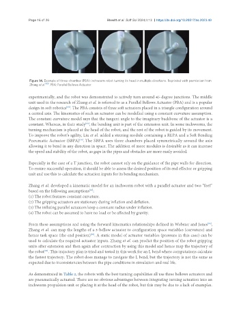
Figure 14. Example of three-chamber (PBA) inchworm robot turning its head in multiple directions. Reprinted with permission from
[65]
Zhang et al. . PBA: Parallel Bellows Actuator.
experimentally, and the robot was demonstrated to actively turn around 45-degree junctions. The middle
unit used in the research of Zhang et al. is referred to as a Parallel Bellows Actuator (PBA) and is a popular
design in soft robotics . The PBA consists of three soft actuators placed in a triangle configuration around
[65]
a central axis. The kinematics of such an actuator can be modelled using a constant curvature assumption.
The constant curvature model says that the tangent angle to the imaginary backbone of the actuator is a
constant. Whereas, in their study , the bending unit is part of the extension unit. In some inchworms, the
[65]
turning mechanism is placed at the head of the robot, and the rest of the robot is guided by its movement.
To improve the robot’s agility, Liu et al. added a steering module containing a REPA and a Soft Bending
[36]
Pneumatic Actuator (SBPA) . The SBPA uses three chambers placed symmetrically around the axis
allowing it to bend in any direction in space. The addition of more modules is desirable as it can increase
the speed and stability of the robot, as gaps in the pipes and obstacles are more easily avoided.
Especially in the case of a T junction, the robot cannot rely on the guidance of the pipe walls for direction.
To ensure successful operation, it should be able to assess the desired position of its end effector or gripping
unit and use this to calculate the actuation inputs for its bending mechanism.
Zhang et al. developed a kinematic model for an inchworm robot with a parallel actuator and two “feet”
based on the following assumptions :
[55]
(1) The robot features constant curvature.
(2) The gripping actuators are stationary during inflation and deflation.
(3) The inflating parallel actuators keep a constant radius under inflation.
(4) The robot can be assumed to have no load or be affected by gravity.
From these assumptions and using the forward kinematics relationships defined in Webster and Jones ,
[66]
Zhang et al. can map the lengths of a 3-bellow actuator to configuration space variables (curvature) and
hence task space (the end position) . A static model of actuator variables (pressure in this case) can be
[67]
used to calculate the required actuator inputs. Zhang et al. can predict the position of the robot gripping
units after extension and then again after contraction by using this model and hence map the trajectory of
the robot . This trajectory plan is tried and tested in this work for an L bend where computations calculate
[55]
the fastest trajectory. The robot does manage to navigate the L bend, but the trajectory is not the same as
expected due to inconsistencies between the pipe conditions in simulation and real life.
As demonstrated in Table 2, the robots with the best turning capabilities all use three bellows actuators and
are pneumatically actuated. There are no obvious advantages between integrating turning actuation into an
inchworm propulsion unit or placing it at the head of the robot, but this may be due to a lack of examples.