
Page 121 - Read Online
P. 121
Peng et al. Soft Sci. 2025, 5, 38 https://dx.doi.org/10.20517/ss.2025.31 Page 7 of 19
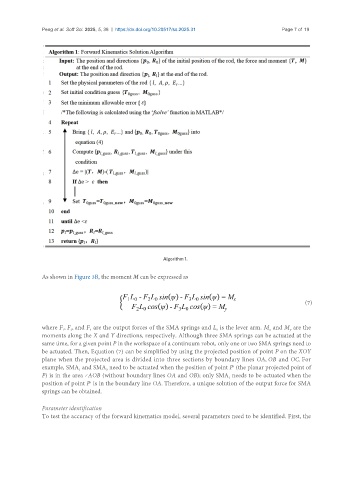
Algorithm 1.
As shown in Figure 3B, the moment M can be expressed as
(7)
where F , F , and F are the output forces of the SMA springs and L is the lever arm. M and M are the
1
y
0
3
2
x
moments along the X and Y directions, respectively. Although three SMA springs can be actuated at the
same time, for a given point P in the workspace of a continuum robot, only one or two SMA springs need to
be actuated. Then, Equation (7) can be simplified by using the projected position of point P on the XOY
plane when the projected area is divided into three sections by boundary lines OA, OB and OC. For
example, SMA and SMA need to be actuated when the position of point P′ (the planar projected point of
3
1
P) is in the area <AOB (without boundary lines OA and OB); only SMA needs to be actuated when the
1
position of point P′ is in the boundary line OA. Therefore, a unique solution of the output force for SMA
springs can be obtained.
Parameter identification
To test the accuracy of the forward kinematics model, several parameters need to be identified. First, the