
Page 86 - Read Online
P. 86
Page 10 of 27 Wang et al. Soft Sci 2024;4:32 https://dx.doi.org/10.20517/ss.2024.15
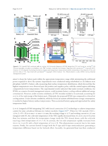
Figure 5. TEC-based BTMS combined with air cooling: (A) Schematic diagrams of BTMS integrating TEC and forced air cooling [32] ; (B)
Physical assembly includes Li-ion battery cells, TEC modules, heatsink, and blowers. Reprinted with permission [62] . Copyright 2017,
Elsevier; (C) 3D diagram illustrating the battery module and temperature measurement points; temperature-time diagram of the cold
and hot sides of TEC. Reprinted with permission [63] . Copyright 2019, Hindawi. TEC: Thermoelectric cooler; BTMS: battery thermal
management system.
aimed to keep the battery pack within the appropriate temperature range while minimizing the additional
power required to drive the system. Experiments were conducted using refurbished 20 Ah lithium iron
phosphate (LiFePO ) battery cells, measuring their surface temperature distribution, which showed that the
4
highest temperatures were observed near the positive and negative poles, with the central region exhibiting
comparatively lower temperatures. The experimental results indicated that under normal conditions, the
BTMS, as a passive thermal management system, could maintain battery cooling without additional energy
consumption. However, under extreme conditions, all TEC modules needed to be activated, accounting for
43.81% of the total energy of the battery pack. Ultimately, the proposed BTMS was compared to a forced air
cooling system. Under extreme conditions, while the forced air system exhibited lower energy consumption,
it resulted in higher battery surface temperatures. This accelerated battery aging and approached the safety
temperature limit.
Li et al. designed a BTMS integrating TEC with forced-convection (F-C) technology to achieve temperature
control for nine cylindrical lithium-ion battery modules [Figure 5C] . When the TEC module (TEC1-
[63]
12706, L × W × H is 40 mm × 40 mm × 3.8 mm, the working voltage is 12 V and working current is 6 A) was
energized with DC, the cold-side temperature of the TEG rapidly decreased from 301.82 to 282.56 K in less
than five minutes, and then the temperature change inside the TEG slowed down, with the cold-side
reaching a limit temperature of 277.71 K. In contrast, the hot-side temperature rapidly increased from
302.01 to 314.03 K, with a limit temperature of 314.22 K. This phenomenon occurred due to two main
reasons. Firstly, the current flowed through both the P-type and N-type semiconductors, generating a
temperature difference based on the Seebeck effect. Secondly, the generated heat was then conducted