
Page 115 - Read Online
P. 115
a b
a
b c c d
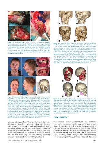
Figure 18: Pruzansky-Kaban Type IIb cases. A Temporal approach Figure 19: Pruzansky-Kaban Type III cases with joint reconstruction.
provides access to both the calvarial bone donor region and to the joint. (a) This patient underwent early joint reconstruction at the age of
Additional submandibular access is not required to osteosynthetize the 4 but did not comply with physiotherapy and was lost to follow-up
costochondral graft to the ascending ramus. (a) The calvarial donor during the next 16 years. He returned with temporomandibular joint
defect is reconstructed using calcium phosphate paste (Hydroset,
Stryker); (b) the joint can be exposed and reconstructed in “open sky” ankylosis and severe tooth decay; (b) the ankylosis was removed and
mode; (c) two osteosynthesis screws have fixed the new condyle to the a new costochondral graft was directed to the original fossa location;
ascending ramus (arrows) (c) frontal view immediately postoperatively of a patient who underwent
late joint reconstruction. She had undergone surgery for plagiocephaly
at a younger age. The joint was relocated more posteriorly and
laterally. As a consequence, the rib graft was inclined at a 30° angle to
the ascending ramus. Healing and postoperative physiotherapy were
uneventful. A mouth opening range of 37 mm was obtained with full
graft union; (d) three-fourths right profile view of the case in (c)
c
a b d
a b
e f g
c d
Figure 20: Pruzansky-Kaban Type III case undergoing a facial rotation
procedure. The ideal profile line according to www.facewizz.com is Figure 21: Pruzansky-Kaban Type III, following joint reconstruction and
coloured blue (g). The targeted profile is colored green. (a) Frontal view, facial rotation. (a) Frontal view showing mirroring with ProPlan CMF. The
relaxed, before facial rotation; (b) left profile view, relaxed, before facial red colored volumes are those with “normal” anatomy on the other side.
rotation; (c) three-fourths profile view of the dental occlusion, before Substantial vault asymmetry exists as this patient was also treated for
facial rotation; (d) three-fourths profile view of the dental occlusion, plagiocephaly in the 1st year of live; (b) three-fourths right profile view.
after facial rotation. Proper prosthetic rehabilitation can be undertaken The transparency shows the underlying original. Nonetheless, it is hoped
secondary to occlusal stability; (e) frontal view, smiling, after facial that the comprehensive treatment planning described in this report may
rotation; (f) profile view, relaxed, after facial rotation; (g) planning of be used to promote optimal patient care ascending ramus; (c) frontal
the advancement. A three-dimensional (3D) computed tomography (CT) view. Implant design in pink; (d) three-fourths profile view. Transparent
reconstruction is layered over the profile cephalogram, which was used implant design indicates the fixation screws
to predict the ideal advancement (blue profile line) and the targeted
advancement (green profile line), based on the risk of postoperative
relapse and the consequences related to dental occlusion DISCUSSION
software of Materialise (Heverlee, Belgium). Layerwise The vertical ramus compartment in hemifacial
3D-Systems (Heverlee, Belgium) prints the implants microsomia can exhibit variable degrees of hard or soft
with porous bone interfaces and sandblasted soft tissue tissue deficiencies. Growth and development result in
interfaces [Figures 21 and 22]. Two important questions distorted proportions in both the transverse and sagittal
during the design process are: (1) is the “normal” jaw angle dimensions. Surgical correction is challenging with respect
excessively prominent and in need of reduction, and (2) to decision-making and execution, but is nonetheless
will the soft tissue (e.g. masseter muscle) deficiency highly rewarding. Older strategies have been tackled by
already be compensated for by adding hardware? newer technologies. The author has witnessed the rise in
Plast Aesthet Res || Vol 2 || Issue 3 || May 15, 2015 105