
Page 36 - Read Online
P. 36
Shanmugasundaram et al. Energy Mater. 2025, 5, 500100 https://dx.doi.org/10.20517/energymater.2024.304 Page 11 of 23
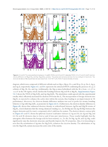
Figure 4. (A and B) The computed band structures; (C and D) PDOS; and (C1 and D1) extracted PDOS (-4 to 4); and (E and F) electron
density difference of Mg ZnSb and Ag- Mg ZnSb systems. The yellow and red area denotes the loss and gain of electrons. The
2 2 2 2
-4
electron densities of the doped material were taken from -4.12 × 10 e/Å. PDOS: Projected density of states.
diagram, which were composed of different orbitals such as Mg-s, Mg-p, Sb-s, and Sb-p, Zn-p, Zn-d, Ag-p,
and Ag-d, respectively. Figure 4C1 and D1 represents the extracted PDOS confirming the presence of s, p, d
orbitals of Mg, Sb, Zn, and Ag. Additionally, the Mg-p states hybridized with the Sb-s from -0.5 eV to
-2.2 eV in the VB region, which clarifies the bonding between Mg and Sb at Mg Sb . Supplementary Figure
2
3
7A-C shows the TDOS of Mg ZnSb and Ag-Mg ZnSb . The simulation results agreed with the experimental
2
2
2
2
results, which effectively increased the electron DOS near the E . The incorporation of foreign elements into
F
Mg Sb is expected to enhance the active sites within the system, thus leading to an improvement in TE
3
2
performance. Moreover, the electron density difference analysis was used to probe the atomic bonding
behavior of Ag with Mg ZnSb , as presented in Figure 4E-F1. Furthermore, the electron density difference in
2
2
Figure 4E1 shows that enhanced electron density is redistributed between Ag/Zn and Mg/Sb atoms of
Mg Sb , which illustrates that the strong chemical bonding (i.e., Zn-Sb/Mg and Zn-Ag-Sb/Mg) between the
2
3
dopant elements and the matrix compound, which stabilizes the system. The electron density contour plot
in [Figure 4E1 and F1] shows the spherical electron localization between (i) Ag and Sb, (ii) Ag and Mg, and
(ii) Zn and Sb elements due to their p and d lone pair interference. These results highlight that the
synergistic effect between the foreign and the host material, i.e., Zn-Sb, Zn-Mg, Ag-Sb, and Ag-Mg, could
significantly tune the electronic structure and thereby improve the TE properties. Also, it is interesting to
note that the substitution of Ag into the Mg ZnSb enhances the electron density. The substitution of Ag
2
2
into the Mg ZnSb system increases the active sites of the matrix.
2
2