
Page 102 - Read Online
P. 102
Yang et al. Energy Mater 2023;3:300029 https://dx.doi.org/10.20517/energymater.2023.10 Page 9 of 18
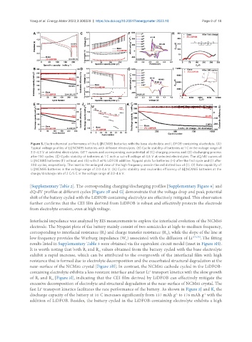
Figure 3. Electrochemical performance of the Li||NCM85 batteries with the base electrolyte and LiDFOB-containing electrolyte. (A)
Typical voltage profiles of Li||NCM85 batteries with different electrolytes. (B) Cyclic stability of batteries at 1 C in the voltage range of
3.0-4.3 V at selected electrolytes. GITT curves and corresponding overpotential of (C) charging process and (D) discharging process
after 150 cycles. (E) Cyclic stability of batteries at 1 C with a cut-off voltage of 4.6 V at selected electrolytes. The dQ/dV curves of
Li||NCM85 batteries (F) without and (G) with 2 wt% LiDFOB additive. Nyquist plots for batteries (H) after the first cycle and (I) after
300 cycles, respectively. The inset is the enlarged view of the high-frequency area in the red dotted box of (I). (J) Rate capability of
Li||NCM85 batteries in the voltage range of 3.0-4.6 V. (K) Cyclic stability and coulombic efficiency of Li||NCM85 batteries at the
charge/discharge rate of 2 C/5 C in the voltage range of 3.0-4.6 V.
[Supplementary Table 2]. The corresponding charging/discharging profiles [Supplementary Figure 6] and
dQ-dV profiles at different cycles [Figure 3F and G] demonstrate that the voltage drop and peak potential
shift of the battery cycled with the LiDFOB-containing electrolyte are effectively mitigated. This observation
further confirms that the CEI film derived from LiDFOB is robust and effectively protects the electrode
from electrolyte erosion, even at high voltage.
Interfacial impedance was analyzed by EIS measurements to explore the interfacial evolution of the NCM85
electrode. The Nyquist plots of the battery mainly consist of two semicircles at high-to-medium frequency,
corresponding to interfacial resistance (R) and charge transfer resistance (R ), while the slope of the line at
ct
f
low frequency provides the Warburg impedance (W ) associated with the diffusion of Li +[74,75] . The fitting
o
results listed in Supplementary Table 3 were obtained via the equivalent circuit model (inset in Figure 3H).
It is worth noting that both R and R values obtained from the battery cycled with the base electrolyte
ct
f
exhibit a rapid increase, which can be attributed to the overgrowth of the interfacial film with high
resistance that is formed due to electrolyte decomposition and the exacerbated structural degradation at the
near-surface of the NCM85 crystal [Figure 3H]. In contrast, the NCM85 cathode cycled in the LiDFOB-
containing electrolyte exhibits a less resistant interface and faster Li transport kinetics with the slow growth
+
of R and R [Figure 3I], indicating that the CEI film derived by LiDFOB can effectively mitigate the
ct
f
excessive decomposition of electrolyte and structural degradation at the near-surface of NCM85 crystal. The
fast Li transport kinetics facilitates the rate performance of the battery. As shown in Figure 3J and K, the
+
-1
-1
discharge capacity of the battery at 10 C increases significantly from 137 mAh g to 176 mAh g with the
addition of LiDFOB. Besides, the battery cycled in the LiDFOB-containing electrolyte exhibits a high