
Page 104 - Read Online
P. 104
Yang et al. Energy Mater 2023;3:300029 https://dx.doi.org/10.20517/energymater.2023.10 Page 11 of 18
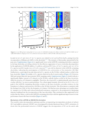
Figure 4. In-situ XRD patterns during the first two cycles of Li||NCM85 batteries (A) without and (B) with LiDFOB. DEMS test of
Li||NCM85 batteries charging to 4.6 V in (C) the base electrolyte and (D) 2 wt% LiDFOB-containing electrolyte.
located at 685 eV and 686.8 eV in F 1s spectra are related to LiF and Li PO F /Li PF , arising from the
x
y
y z
x
decomposition of lithium salt (LiPF ) in the electrolyte [71,83] . The intensity of these peaks, represented by the
6
peak area [Supplementary Figure 8], is significantly lower in the LiDFOB-containing electrolyte compared
to the base electrolyte, providing evidence for the effective suppression of severe electrolyte decomposition
by the application of LiDFOB additive. In addition, additional B-F (684.5 eV in F 1s spectra and 192.7 eV in
B 1s spectra) and B-O peaks (190.5 eV in B 1s spectra) [52,73] can only be observed in the LiDFOB-containing
electrolyte, indicating the participation of LiDFOB in the construction of the protective CEI film.
Furthermore, a peak signal was also detected in B 1s spectra on the NCM85 cathode surface cycled in the
base electrolyte [Figure 5J], similar to B 1s spectra observed on the Li anode surface [Figure 2G]. However,
SEM and energy dispersive spectrometer (EDS)-mapping results [Supplementary Figure 9] clearly indicate a
significantly higher amount of P element on the NCM85 cathode surface cycled in the base electrolyte,
while the presence of B element is negligible. Therefore, the observed B 1s signal primarily arises from the
overlap with the P 2s spectra peak positions. The robust signal intensity observed at the M-O (530.3 eV)
peak in the LiDFOB-containing electrolyte, relative to the base electrolyte, provides evidence for the
formation of a thinner and protective CEI film on the NCM85 electrode. This observation is consistent with
the findings from TEM. In fact, the formation of a thinner CEI film has some advantages as it enables faster
+
Li transport in CEI film and reduced interfacial resistances compared to the progressively thickening
deposits resulting from the decomposition of the base electrolyte. This conclusion is also supported by the
results that the battery cycled in the LiDFOB-containing electrolyte exhibits significant improvement in rate
performance than in the base electrolyte [Figure 3J and K].
Mechanism of the LiDFOB on SEI/CEI film formation
The possible redox decomposition pathways and the corresponding decomposition products of solvent
(EC) and additive molecule (DFOB ) were investigated by density functional theory (DFT) calculation. It
-
shows that the preferential reduction of DFOB triggers the decomposition of EC on the anode side
-