


Page 64 - Read Online
P. 64
Dong et al. Energy Mater.  2026, 6, 600026                                        Page 9 of 16


               in the untreated sample are relatively small, whereas after introducing 0.05 mol L  NdCl , the grain size
                                                                                       -1
                                                                                             3
               increases significantly, indicating that NdCl  treatment promotes grain growth. A more complete
                                                        3
               comparison of grain morphologies across the concentration series is provided in Supplementary Figure 8.
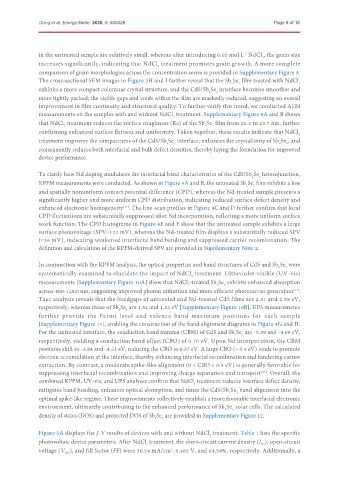
               The cross-sectional SEM images in Figure 3H and I further reveal that the Sb Se  film treated with NdCl 3
                                                                                     3
                                                                                  2
               exhibits a more compact columnar crystal structure, and the CdS/Sb Se  interface becomes smoother and
                                                                             3
                                                                          2
               more tightly packed; the visible gaps and voids within the film are markedly reduced, suggesting an overall
               improvement in film continuity and structural quality. To further verify this trend, we conducted AFM
               measurements on the samples with and without NdCl  treatment. Supplementary Figure 9A and B shows
                                                              3
               that NdCl  treatment reduces the surface roughness (Ra) of the Sb Se  film from 26.3 to 23.7 nm, further
                       3
                                                                         2
                                                                            3
               confirming enhanced surface flatness and uniformity. Taken together, these results indicate that NdCl 3
               treatment improves the compactness of the CdS/Sb Se  interface, enhances the crystallinity of Sb Se , and
                                                              3
                                                                                                      3
                                                           2
                                                                                                   2
               consequently reduces both interfacial and bulk defect densities, thereby laying the foundation for improved
               device performance.
               To clarify how Nd doping modulates the interfacial band characteristics of the CdS/Sb Se  heterojunction,
                                                                                         2
                                                                                            3
               KPFM measurements were conducted. As shown in Figure 4A and B, the untreated Sb Se  film exhibits a low
                                                                                          3
                                                                                       2
               and spatially nonuniform contact potential difference (CPD), whereas the Nd-treated sample presents a
               significantly higher and more uniform CPD distribution, indicating reduced surface defect density and
               enhanced electronic homogeneity . The line-scan profiles in Figure 4C and D further confirm that local
                                            [43]
               CPD fluctuations are substantially suppressed after Nd incorporation, reflecting a more uniform surface
               work function. The CPD histograms in Figure 4E and F show that the untreated sample exhibits a large
               surface photovoltage (SPV≈122 mV), whereas the Nd-treated film displays a substantially reduced SPV
               (≈36 mV), indicating weakened interfacial band bending and suppressed carrier recombination. The
               definition and calculation of the KPFM-derived SPV are provided in Supplementary Note 2.


               In conjunction with the KPFM analysis, the optical properties and band structures of CdS and Sb Se  were
                                                                                                   2
                                                                                                     3
               systematically examined to elucidate the impact of NdCl  treatment. Ultraviolet-visible (UV-vis)
                                                                    3
               measurements [Supplementary Figure 10A] show that NdCl -treated Sb Se  exhibits enhanced absorption
                                                                             2
                                                                                3
                                                                   3
               across 400-1,000 nm, suggesting improved photon utilization and more efficient photocarrier generation .
                                                                                                        [44]
               Tauc analysis reveals that the bandgaps of untreated and Nd-treated CdS films are 2.31 and 2.38 eV,
               respectively, whereas those of Sb Se  are 1.34 and 1.22 eV [Supplementary Figure 10B]. UPS measurements
                                           2
                                             3
               further   provide   the   Fermi   level   and   valence   band   maximum   positions   for   each   sample
               [Supplementary Figure 11], enabling the construction of the band alignment diagrams in Figure 4G and H.
               For the untreated interface, the conduction band minima (CBM) of CdS and Sb Se  are -3.39 and -4.09 eV,
                                                                                      3
                                                                                   2
               respectively, yielding a conduction band offset (CBO) of 0.70 eV. Upon Nd incorporation, the CBM
               positions shift to -3.84 and -4.21 eV, reducing the CBO to 0.37 eV. A large CBO (> 0.4 eV) tends to promote
               electron accumulation at the interface, thereby enhancing interfacial recombination and hindering carrier
               extraction. By contrast, a moderate spike-like alignment (0 < CBO < 0.4 eV) is generally favorable for
               suppressing interfacial recombination and improving charge separation and transport . Overall, the
                                                                                             [45]
               combined KPFM, UV-vis, and UPS analyses confirm that NdCl  treatment reduces interface defect density,
                                                                     3
               mitigates band bending, enhances optical absorption, and tunes the CdS/Sb Se  band alignment into the
                                                                                    3
                                                                                 2
               optimal spike-like regime. These improvements collectively establish a more favorable interfacial electronic
               environment, ultimately contributing to the enhanced performance of Sb Se  solar cells. The calculated
                                                                                   3
                                                                                2
               density of states (DOS) and projected DOS of Sb Se  are provided in Supplementary Figure 12.
                                                       2
                                                          3
               Figure 5A displays the J-V results of devices with and without NdCl  treatment. Table 1 lists the specific
                                                                           3
               photovoltaic device parameters. After NdCl  treatment, the short-circuit current density (J ), open-circuit
                                                    3
                                                                                             SC
               voltage (V ), and fill factor (FF) were 30.54 mA/cm , 0.465 V, and 64.58%, respectively. Additionally, a
                                                             2
                        OC

