


Page 15 - Read Online
P. 15
Page 12 of 39                          Yang et al. Soft Sci. 2025, 5, 46  https://dx.doi.org/10.20517/ss.2025.44

               categorized into two types: one in which the loss occurs due to deformation and another in which the loss
               occurs due to absorption of light by the material.

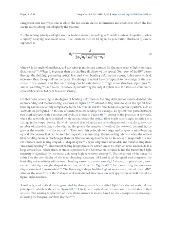
               For the sensing principle of light loss due to deformation, according to Maxwell’s system of equations, when
               a rapidly decaying evanescent wave (EW) exists in the low RI layer, its penetration thickness d  can be
                                                                                                   p
               expressed as


                                                                                                        (1)


               where θ is the angle of incidence, and the other quantities are constant for the same beam of light entering a
                      l
               fixed sensor . When d  is greater than the cladding thickness of the optical fiber, part of the EW passes
                         [109]
                                    p
               through the cladding, generating optical loss, and when bending deformation occurs, θ decreases while d
                                                                                                         p
                                                                                          l
               increases; thus, the optical loss increases. The change in optical loss corresponds to the change in strain or
               stress in the sensor, and this relationship can be established through reconstruction algorithms ,
                                                                                                       [124]
               simulation fitting , and so on. Therefore, by monitoring the output optical loss, the stress or strain in the
                              [125]
               optical fiber can be fed back to realize sensing.
               On this basis, according to the degree of bending deformation, bending deformation can be divided into
               microbending and macrobending, as shown in Figure 5A . Microbending refers to when the optical fiber
                                                                [126]
               bending radius is relatively comparable to the fiber radius and the fiber bends in a periodic pattern, such as
               sawtooth or corrugated. In the case of sawtooth microbending, for example, an optical fiber passes between
               two toothed plates with a mechanical cycle, as shown in Figure 5B . Owing to the presence of sawteeth,
                                                                        [119]
               when the sawtooth layer is shifted by an external force, the optical fiber bends accordingly, resulting in a
               change in the output power. Hu et al. reported that when the microbending period is set, the greater the
               number of microbending cycles (that is, the greater the number of teeth of the sawtooth pattern) is, the
               greater the sensitivity of the sensor . They used this principle to design and prepare a microbending
                                              [119]
               optical fiber sensor that can be used for respiratory monitoring. Macrobending refers to when the optical
               fiber bending radius is much larger than the fiber radius, approximately on the order of magnitude of a few
               centimeters, such as ring-shaped, U-shaped, spiral , equal-amplitude sinusoidal, and variable-amplitude
                                                          [127]
                               [128]
               sinusoidal bending . This macrobending design places the sensor under no strain or stress and results in a
               large optical loss. When strain or stress is generated, the deformation is reduced, and the transmitted light
               intensity is significantly increased, achieving high-sensitivity sensing . The sensitivity of the sensor is
                                                                            [129]
               related to the complexity of the macrobending structure. Al-Lami et al. designed and compared the
               feasibility and sensitivity of four macrobending sensor structures, namely, U-shaped, droplet-shaped, knot-
               shaped, and figure-eight shaped structures, as shown in Figure 5C , for monitoring the curvature
                                                                            [130]
               displacements of human joints . The figure-eight shape had the highest sensor sensitivity of -0.477 dB/°,
                                         [130]
               whereas the sensitivity of the U-shaped and knot-shaped structures was only approximately half that of the
               figure-eight structure.

               Another type of optical loss is generated by absorption of transmitted light by a dopant material, the
               principle of which is shown in Figure 5D . This type of optical loss is common in stretchable optical
                                                   [131]
               sensors. The sensing mechanism of these strain sensors is mostly based on dye absorption spectroscopy,
               following the Bouguer–Lambert–Beer law :
                                                  [132]

