
Page 97 - Read Online
P. 97
Kim et al. Soft Sci 2024;4:33 https://dx.doi.org/10.20517/ss.2024.28 Page 21 of 31
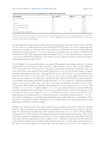
Table 4. Summary of the characteristics of published data on OLEDs with CuI-based HIL
HIL materials CE max (cd·A ) EQE (%) Year ref.
-1
20% CuI-doped NPB 69 17.5 2008 [126]
[124]
CuI 2.68 - 2010
a [127]
12 nm CuI 2 2012
[125]
10% CuI-doped m-MTDATA 10.4 - 2017
[129]
25 wt.% CuI-doped CuSCN 16.8 - 2018
CuI:CuPC 70 18.5 2020 [130]
[128]
110 °C annealed nanocrystalline CuI 62 17 2022
a -2 -2
4,000 cd·m at 200 mA·cm . OLEDs: CuI: Copper iodide; HIL: hole injection layer; EQE: external quantum efficiency; NPB: 1,4-bis[N-(1-
naphthyl)-N’-phenylamino]-4,4’-diamine; m-MTDATA: 4,4’,4’’-tris(N-3-methylphenyl-N-phenyl-amino)triphenylamine; CuSCN: copper
thiocyanate; CuPC: copper (II) phthalocyanine.
CuI was dissolved in ACN and spin-coated without post-annealing. In this study, the PCE of solar cells with
CuI HTLs was 16.8%, while that of solar cells with PEDOT:PSS HTLs was 13.6%. These results suggest the
potential of a CuI layer as a HTL for flexible solar cells due to its flexibility, low process temperature and
acceptable electrical properties . Hu et al. reported on perovskite solar cells with a CuI/PEDOT:PSS
[132]
double layer for HTL. Their experiments indicated a higher PCE of 14.3% for the double layer, compared to
12.9% for the PEDOT:PSS single layer. The stability was also enhanced, with the initial performance
maintaining around 88% after 720 h .
[133]
In 2018, Haider et al. conducted simulations on various HTL materials for perovskite solar cells. The results
indicated that the PCE of devices with a CuI HTL could reach up to 21.32%. They compared PEDOT,
PTAA, Spiro-MeOTAD, P3HT, and CuI. This paper compared the published experimental results; the
PCEs of the devices with each HTL were similar, raging from 15% to 20% with Pb-based organic-inorganic
hybrid perovskite photoactive layers. Although the PCE of solar cells with CuI (17.6%) was slightly lower
than that with PTAA (20.2%), the cost of PTAA was more than 600 times higher than that of CuI.
Moreover, the stability of CuI is also better than that of others. PEDOT:PSS, PTAA, and Spiro-MeOTAD
are not stable with humidity, and P3HT is weak under heat . In 2020, Haider et al. conducted simulations
[131]
again on inverted perovskite solar cells with a CuI HTL, investigating the effects of hole carrier
concentration, Hall mobility, and thickness. They optimized the carrier concentration to 1 × 10 cm , Hall
-3
19
2
-1 -1
-2
-3
mobility to 1 × 10 cm ·V ·s , defect density to 1 × 10 cm , and optical thickness to 100 nm. With these
14
optimized conditions, the performance of the solar cell achieved a short-circuit current density (J ) of
SC
20.08 mA·cm , open circuit voltage (V ) of 1.17 V, fill factor (FF factor) of 89.45% and PCE of 21.32%.
-2
OC
18
-3
Regarding carrier concentration, the J increased with carrier concentration and saturated at 1 × 10 cm .
SC
The carrier recombination rate and the energy band height also changed with carrier concentration. When
the carrier concentration reached a sufficient level, the recombination rate no longer significantly affected
performance, and the J remained constant .
[134]
SC
Khadka et al. reported on solar cells with an ammonia-aqueous solution-processed CuI HTL for a flexible
substrate. They revealed that the morphology and crystallinity of the perovskite layer grown on the CuI
layer were affected by the morphology of the CuI layer. They tested 0.025, 0.05, and 0.1 M CuI solutions,
finding that the 0.05 M CuI solution produced the smoothest surface and best performance. The 0.025 M
CuI solution resulted in a small grain size, while the 0.1 M CuI solution produced a rough surface. The PCE
of the solar cell with an optimized CuI HTL reached 14.21% . Mahdy et al. reported a CuI HTL fabricated
[135]
using a solution iodination process with an iodine/ethanol solution for 1 h. They optimized the thickness of
the CuI in an inverted planar perovskite solar cell, achieving a PCE of 0.76%. The relatively low