
Page 127 - Read Online
P. 127
Peng et al. Soft Sci. 2025, 5, 38 https://dx.doi.org/10.20517/ss.2025.31 Page 13 of 19
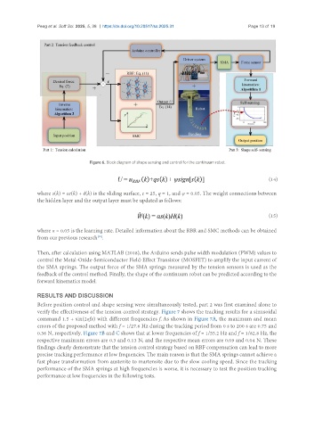
Figure 6. Block diagram of shape sensing and control for the continuum robot.
(14)
where s(k) = ce(k) + e(k) is the sliding surface, c = 25, q = 1, and ψ = 0.05. The weight connections between
the hidden layer and the output layer must be updated as follows:
(15)
where α = 0.05 is the learning rate. Detailed information about the RBR and SMC methods can be obtained
from our previous research .
[35]
Then, after calculation using MATLAB (2018), the Arduino sends pulse width modulation (PWM) values to
control the Metal-Oxide-Semiconductor Field-Effect Transistor (MOSFET) to amplify the input current of
the SMA springs. The output force of the SMA springs measured by the tension sensors is used as the
feedback of the control method. Finally, the shape of the continuum robot can be predicted according to the
forward kinematics model.
RESULTS AND DISCUSSION
Before position control and shape sensing were simultaneously tested, part 2 was first examined alone to
verify the effectiveness of the tension control strategy. Figure 7 shows the tracking results for a sinusoidal
command 1.5 + sin(2πfx) with different frequencies f. As shown in Figure 7A, the maximum and mean
errors of the proposed method with f = 1/27.6 Hz during the tracking period from 0 s to 200 s are 0.75 and
0.36 N, respectively. Figure 7B and C shows that at lower frequencies of f = 1/55.2 Hz and f = 1/82.8 Hz, the
respective maximum errors are 0.3 and 0.13 N, and the respective mean errors are 0.09 and 0.04 N. These
findings clearly demonstrate that the tension control strategy based on RBF compensation can lead to more
precise tracking performance at low frequencies. The main reason is that the SMA springs cannot achieve a
fast phase transformation from austenite to martensite due to the slow cooling speed. Since the tracking
performance of the SMA springs at high frequencies is worse, it is necessary to test the position tracking
performance at low frequencies in the following tests.