
Page 109 - Read Online
P. 109
Page 12 of 19 Hussain et al. Soft Sci. 2025, 5, 21 https://dx.doi.org/10.20517/ss.2025.02
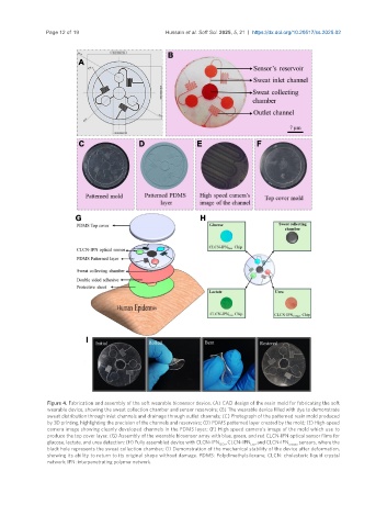
Figure 4. Fabrication and assembly of the soft wearable biosensor device. (A) CAD design of the resin mold for fabricating the soft
wearable device, showing the sweat collection chamber and sensor reservoirs; (B) The wearable device filled with dye to demonstrate
sweat distribution through inlet channels and drainage through outlet channels; (C) Photograph of the patterned resin mold produced
by 3D printing, highlighting the precision of the channels and reservoirs; (D) PDMS patterned layer created by the mold; (E) High-speed
camera image showing cleanly developed channels in the PDMS layer; (F) High speed camera’s image of the mold which use to
produce the top cover layer; (G) Assembly of the wearable biosensor array with blue, green, and red CLCN-IPN optical sensor films for
glucose, lactate, and urea detection; (H) Fully assembled device with CLCN-IPN GOx , CLCN-IPN , and CLCN-IPN urease sensors, where the
Lox
black hole represents the sweat collection chamber; (I) Demonstration of the mechanical stability of the device after deformation,
showing its ability to return to its original shape without damage. PDMS: Polydimethylsiloxane; CLCN: cholesteric liquid crystal
network; IPN: interpenetrating polymer network.