
Page 108 - Read Online
P. 108
Hussain et al. Soft Sci. 2025, 5, 21 https://dx.doi.org/10.20517/ss.2025.02 Page 11 of 19
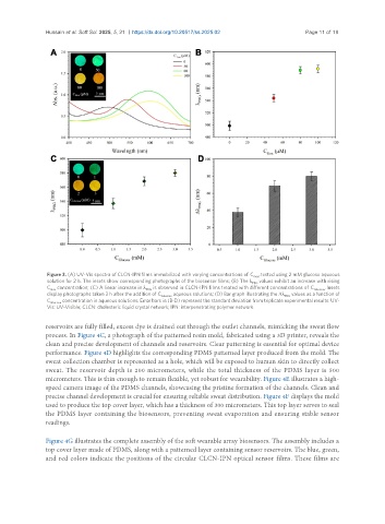
Figure 3. (A) UV-Vis spectra of CLCN-IPN films immobilized with varying concentrations of C Gox , tested using 2 mM glucose aqueous
solution for 2 h. The insets show corresponding photographs of the biosensor films; (B) The λ PBG values exhibit an increase with rising
C Gox concentration; (C) A linear increase in λ PBG is observed in CLCN-IPN films treated with different concentrations of C Glucose . Insets
display photographs taken 2 h after the addition of C Glucose aqueous solutions; (D) Bar graph illustrating the Δλ PBG values as a function of
C Glucose concentration in aqueous solutions. Error bars in (B-D) represent the standard deviation from triplicate experimental results. UV-
Vis: UV-Visible; CLCN: cholesteric liquid crystal network; IPN: interpenetrating polymer network.
reservoirs are fully filled, excess dye is drained out through the outlet channels, mimicking the sweat flow
process. In Figure 4C, a photograph of the patterned resin mold, fabricated using a 3D printer, reveals the
clean and precise development of channels and reservoirs. Clear patterning is essential for optimal device
performance. Figure 4D highlights the corresponding PDMS patterned layer produced from the mold. The
sweat collection chamber is represented as a hole, which will be exposed to human skin to directly collect
sweat. The reservoir depth is 200 micrometers, while the total thickness of the PDMS layer is 500
micrometers. This is thin enough to remain flexible, yet robust for wearability. Figure 4E illustrates a high-
speed camera image of the PDMS channels, showcasing the pristine formation of the channels. Clean and
precise channel development is crucial for ensuring reliable sweat distribution. Figure 4F displays the mold
used to produce the top cover layer, which has a thickness of 300 micrometers. This top layer serves to seal
the PDMS layer containing the biosensors, preventing sweat evaporation and ensuring stable sensor
readings.
Figure 4G illustrates the complete assembly of the soft wearable array biosensors. The assembly includes a
top cover layer made of PDMS, along with a patterned layer containing sensor reservoirs. The blue, green,
and red colors indicate the positions of the circular CLCN-IPN optical sensor films. These films are