
Page 828 - Read Online
P. 828
Ancona et al. Mini-invasive Surg 2020;4:79 I http://dx.doi.org/10.20517/2574-1225.2020.80 Page 17 of 23
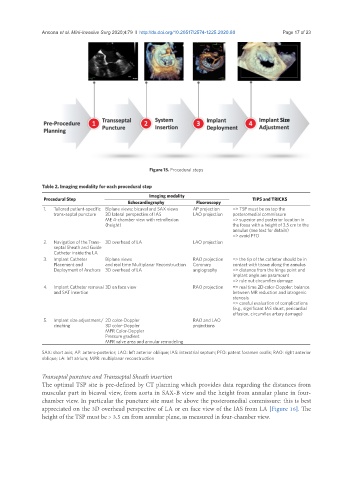
Figure 15. Procedural steps
Table 2. Imaging modality for each procedural step
Imaging modality
Procedural Step TIPS and TRICKS
Echocardiography Fluoroscopy
1. Tailored patient-specific Biplane views: bicaval and SAX views AP projection => TSP must be on top the
trans-septal puncture 3D lateral perspective of IAS LAO projection posteromedial commissure
ME 4-chamber view with retroflexion => superior and posterior location in
(height) the fossa with a height of 3.5 cm to the
annulus (see text for details)
=> avoid PFO
2. Navigation of the Trans- 3D overhead of LA LAO projection
septal Sheath and Guide
Catheter inside the LA
3. Implant Catheter Biplane views RAO projection => the tip of the catheter should be in
Placement and and real time Multiplanar Reconstruction Coronary contact with tissue along the annulus
Deployment of Anchors 3D overhead of LA angiography => distance from the hinge point and
implant angle are paramount
=> rule out circumflex damage
4. Implant Catheter removal 3D en face view RAO projection => real time 2D color-Doppler: balance
and SAT insertion between MR reduction and iatrogenic
stenosis
=> careful evaluation of complications
(e.g., significant IAS shunt, pericardial
effusion, circumflex artery damage)
5. Implant size adjustment/ 2D color-Doppler RAO and LAO
cinching 3D color-Doppler projections
MPR Color-Doppler
Pressure gradient
MPR valve area and annular remodeling
SAX: short axis; AP: antero-posterior; LAO: left anterior oblique; IAS: interatrial septum; PFO: patent foramen ovalis; RAO: right anterior
oblique; LA: left atrium; MPR: multiplanar reconstruction
Transeptal puncture and Transseptal Sheath insertion
The optimal TSP site is pre-defined by CT planning which provides data regarding the distances from
muscular part in bicaval view, from aorta in SAX-B view and the height from annular plane in four-
chamber view. In particular the puncture site must be above the posteromedial commissure: this is best
appreciated on the 3D overhead perspective of LA or en face view of the IAS from LA [Figure 16]. The
height of the TSP must be > 3.5 cm from annular plane, as measured in four-chamber view.