
Page 829 - Read Online
P. 829
Page 18 of 23 Ancona et al. Mini-invasive Surg 2020;4:79 I http://dx.doi.org/10.20517/2574-1225.2020.80
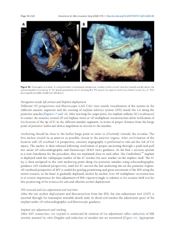
Figure 16. Transseptal puncture. A: posteromedial commissural perspective: tenting (white arrow) must be located exactly above the
posteromedial commissure; B: 3D lateral perspective of LA showing the TSS across the septum (with the dilator) inside the LA. TSS:
transseptal steerable sheath; LA: left atrium
Navigation inside left atrium and Implant deployment
Different 3D perspectives and fluoroscopic LAO CAU view enable visualization of the system in the
different annular segments and the steering of implant delivery system (IDS) inside the LA along the
posterior annulus [Figures 17 and 18]. After reaching the target point, the implant catheter (IC) is advanced
to contact the annulus: several 2D and biplane views or 3D multiplanar reconstruction allow verification of
the location of the tip of IC in the different annular segments, in terms of proper distance from the hinge
point of posterior leaflet and device angulation in relation to the annulus.
Anchoring should be close to the leaflet hinge point in order to effectively remodel the annulus. The
first anchor should be as anterior as possible, closest to the anterior trigone. After confirmation of the
location with 3D overhead LA perspective, coronary angiography is performed to rule out the risk of CA
injury. The anchor is then released following verification of proper anchoring through a push-and-pull
test under 2D echocardiographic and fluoroscopic (RAO view) guidance. As the first 3 anchors operate
TM
as a root foundation for the procedure, they are implanted close to each other. The Cardioband implant
is deployed until the radiopaque marker of the IC reaches the next marker on the implant itself. The IC
tip is then navigated to the next anchoring point along the posterior annulus using echocardiographic
guidance (3D overhead perspective), until the IC reaches the last anchoring site on the posterior trigone.
3D overhead perspective of MV is useful for guiding positioning and gross movement of the IDS along the
mitral annulus, as the band is gradually deployed, anchor by anchor. Live 3D multiplanar reconstruction
is of utmost importance for fine adjustment of IDS trajectory/angle in relation to the annular shelf and for
fine positioning of the annulus for safe and effective anchor deployment.
IDS removal and size adjustment tool insertion
After the last anchor deployment and disconnection from the IDS, the size adjustment tool (SAT) is
inserted through the transseptal steerable sheath until its distal end reaches the adjustment spool of the
implant under 3D echocardiographic and fluoroscopic guidance.
Implant size adjustment and cinching
After SAT connection, the implant is contracted by rotation of the adjustment roller: reduction of MR
severity assessed by color-Doppler and reduction of annulus size are monitored [Figure 19]. Appropriate