


Page 165 - Read Online
P. 165
Wang et al. J. Mater. Inf. 2026, 6, 13                                            Page 9 of 19


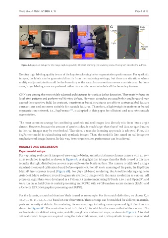
                Figure 8. Equipment setups for (A) image capturing and (B) 3D mesh scanning (C) rendering scene. Photograph taken by the authors.


               Keeping high labeling quality is one of the keys to achieving better segmentation performance. For synthetic
               images, the labels can be generated directly from the rendering settings, but there are situations where
               multiple adjacent pixels could be the boundary as the scratch cross-section covers a certain area. In these
               cases, larger labeling areas are preferred rather than smaller ones to include all the boundary features.


               CNNs are among the most widely adopted architectures for surface defect detection. They mainly focus on
               local pixel patterns and perform well for tiny defects. However, scratches are usually thin and long and may
               exceed the receptive field. In contrast, transformer-based structures are able to capture global feature
               connections and are more suitable for scratch features. Therefore, a lightweight transformer-based
               segmentation network, i.e., SegFormer , is adopted in this paper for efficient and accurate scratch
                                                  [35]
               segmentation.

               The most common strategy for combining synthetic and real images is to directly mix them into a single
               dataset. However, because the amount of synthetic data is much larger than that of real data, unique features
               in the real images may be overlooked. Therefore, a transfer learning approach is adopted. First, the
               SegFormer model is trained using only synthetic images. Then, the model is fine-tuned on real images to
               emphasize real-image features. In this way, better segmentation performance can be achieved.


               RESULTS AND DISCUSSION
               Experimental setups
               For capturing real scratch images of aero-engine blades, an industrial monochrome camera with 5,120 ×
               5,120 resolution is applied as shown in Figure 8A. A ring light that is larger than the blade is used in this case
               to make the light distribution as even as possible on the blade surface. The camera is calibrated using a
               standard chessboard calibration board before experiment. For 3D mesh scanning of the parts, the RigelScan
               Max 3D laser scanner is used [Figure 8B]. For physical-based rendering, the Arnold rendering engine in
               Autodesk Maya software is used to generate synthetic images with the same resolution as camera. All
               proposed algorithms were developed in a Python 3.8 environment using PyTorch 1.10.1 and OpenCV, and
               were run on an Intel Core i9 central processing unit (CPU) with 64 GB random-access memory (RAM) and
               a GeForce RTX 3060 graphics processing unit (GPU).

               For the datasets, a scratched titanium blade is used as an example. For the scratch definition, we choose F  =
                                                                                                        N
               40, H  = 35, w = 0.8, A = 0.6 based on our observation. These settings can be modified for different materials,
                   V
               parts and severity of defects. For rendering, the scene settings, including camera pose and light direction, are
               shown in Figure 8C. The resolution is set to 5,120 × 5,120, which is the same as that of the camera. The
               surface texture is defined using color, metallic, roughness, and normal maps, as shown in Figure 6. A total of
               200 real scratch images are acquired using the industrial camera, and 1,200 synthetic images are generated

