


Page 161 - Read Online
P. 161
Wang et al. J. Mater. Inf. 2026, 6, 13                                            Page 5 of 19


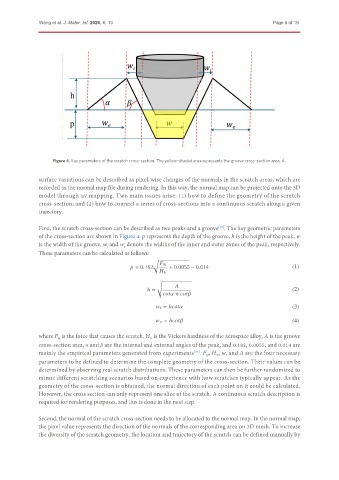
                    Figure 4. Key parameters of the scratch cross-section. The yellow-shaded area represents the groove cross-section area, A.

               surface variations can be described as pixel-wise changes of the normals in the scratch areas, which are
               recorded in the normal map file during rendering. In this way, the normal map can be projected onto the 3D
               model through uv mapping. Two main issues arise: (1) how to define the geometry of the scratch
               cross-section; and (2) how to connect a series of cross-sections into a continuous scratch along a given
               trajectory.


               First, the scratch cross-section can be described as two peaks and a groove . The key geometric parameters
                                                                              [33]
               of the cross-section are shown in Figure 4: p represents the depth of the groove, h is the height of the peak, w
               is the width of the groove, w and w  denote the widths of the inner and outer zones of the peak, respectively.
                                       i
                                             e
               These parameters can be calculated as follows:
                                                       √

                                                  = 0.182   + 0.0055 − 0.014                            (1)

                                                        √

                                                     ℎ =                                                (2)
                                                                   +

                                                              = ℎ                                       (3)

                                                              = ℎ                                       (4)

               where F  is the force that causes the scratch, H  is the Vickers hardness of the aerospace alloy, A is the groove
                                                      V
                     N
               cross-section area, α and β are the internal and external angles of the peak, and 0.182, 0.0055, and 0.014 are
               mainly the empirical parameters generated from experiments . F , H , w, and A are the four necessary
                                                                     [33]
                                                                         N
                                                                             V
               parameters to be defined to determine the complete geometry of the cross-section. Their values can be
               determined by observing real scratch distributions. These parameters can then be further randomized to
               mimic different scratching scenarios based on experience with how scratches typically appear. As the
               geometry of the cross-section is obtained, the normal direction of each point on it could be calculated.
               However, the cross section can only represent one slice of the scratch. A continuous scratch description is
               required for rendering purposes, and this is done in the next step.


               Second, the normal of the scratch cross-section needs to be allocated to the normal map. In the normal map,
               the pixel value represents the direction of the normals of the corresponding area on 3D mesh. To increase
               the diversity of the scratch geometry, the location and trajectory of the scratch can be defined manually by

