


Page 160 - Read Online
P. 160
Page 4 of 19                                                     Wang et al. J. Mater. Inf. 2026, 6, 13


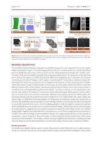
               Figure 3. Workflow of the proposed physical synthetic image generation and utilization method, including 3D model and texture definition,
               physically based rendering, generated image processing, image quality assessment, and segmentation model development. PSNR: Peak
               signal-to-noise ratio; SSIM: structural similarity index metric.

               MATERIALS AND METHODS
               The workflow of generating and using physical synthetic images for scratch segmentation of aero-engine
               blades is presented in Figure 3. First, the imaging characteristics of a complex product are mainly determined
               by its 3D geometry and surface textures, which are the subtle geometrical changes on a smaller scale.
               Therefore, both aspects should be modeled in the image generation process. The geometry can be described
               by 3D meshes. For textures, it is difficult to directly define it on complex surfaces. In practice, the 3D mesh
               can be projected onto 2D images (called maps) using through UV mapping, a common strategy for
               rendering tasks. In this way, each pixel in the 2D images can be linked to a specific location in the 3D model.
               Color maps, metallic maps, roughness maps, normal maps, and other maps can then be defined to describe
               different aspects of the surface texture. Scratches are typical textural features, where the surface normal of
               scratched areas is altered, producing their visual effects. Therefore, scratches can be represented on the
               normal maps. Based on this approach, a scratch generation tool is developed, allowing users to draw random
               lines as scratch trajectories on the normal map, which are then projected onto the blade surface for
               rendering. Second, with the geometry and texture model of the aero-engine blades, the camera, light, and
               ambient light are defined for rendering purposes. As the purpose of rendering is to generate images close to
               real ones, the rendering scene should mimic actual shooting conditions. The settings can also be customized
               to cover different practical scenarios. As the rendering pipeline is well-developed in commercial software
               such as Autodesk Maya, we directly use it to generate rendered images. Third, the generated rendered images
               are preprocessed by cropping the scratched areas and performing pixel-level labeling. Fourth, the rendered
               image quality should be assessed before the training process, as it influences segmentation performance.
               Finally, with sufficient high-quality synthetic images, the segmentation model can be trained. A
               transformer-based network is chosen because it captures global feature connections better than
               convolution-based models . Meanwhile, transfer learning is applied instead of directly mixing real and
                                      [6]
               synthetic images to achieve better performance on real scratch images. The key steps are detailed as follows.

               Scratch generation
               As scratches are usually shallow and do not alter the geometry of the blade, they can be represented as
               changes to the mesh normals of a local region while keeping vertex positions unchanged. These subtle

