
Page 114 - Read Online
P. 114
Songthumjitti et al. Intell Robot 2023;3(3):306-36 I http://dx.doi.org/10.20517/ir.2023.20 Page 11 of 31
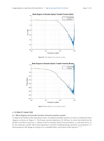
Figure 10. Gain diagram of an actuator system.
Figure 11. Phase diagram of an actuator system.
4. STABILITY ANALYSIS
4.1. Block diagram and transfer function of human-machine system
To analyze the stability of the experiment system, including the human operator, we need to consider the block
diagram, as shown in FFigure 12. The human operator impedance, , will react to errors that result from the
absolute end-effector position, , subtract from the operator-hand intended position, , and create force, ℎ,
for the admittance model, where hand impedance is used for modeling human operators as in Equation (11).
Each parameter will change according to the controlled object and posture of the operator [18,19] .