
Page 119 - Read Online
P. 119
Page 16 of 31 Songthumjitti et al. Intell Robot 2023;3(3):306-36 I http://dx.doi.org/10.20517/ir.2023.20
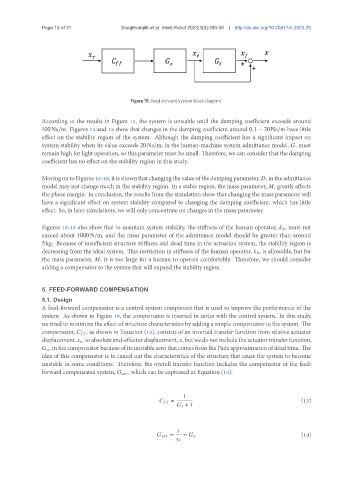
Figure 19. Feed-forward system block diagram.
According to the results in Figure 13, the system is unstable until the damping coefficient exceeds around
100 Ns/m. Figures 14 and 15 show that changes in the damping coefficient around 0.1 − 20 Ns/m have little
effect on the stability region of the system. Although the damping coefficient has a significant impact on
system stability when its value exceeds 20 Ns/m, in the human-machine system admittance model, , must
remain high for light operation, so this parameter must be small. Therefore, we can consider that the damping
coefficient has no effect on the stability region in this study.
MovingontoFigures16-18, itisshownthatchangingthevalueofthedampingparameter, , intheadmittance
model may not change much in the stability region. In a stable region, the mass parameter, , greatly affects
the phase margin. In conclusion, the results from the simulation show that changing the mass parameter will
have a significant effect on system stability compared to changing the damping coefficient, which has little
effect. So, in later simulations, we will only concentrate on changes in the mass parameter.
Figures 16-18 also show that to maintain system stability, the stiffness of the human operator, ℎ, must not
exceed about 1000 N/m, and the mass parameter of the admittance model should be greater than around
5 kg. Because of insufficient structure stiffness and dead time in the actuation system, the stability region is
decreasing from the ideal system. This restriction in stiffness of the human operator, ℎ, is allowable, but for
the mass parameter, , it is too large for a human to operate comfortably. Therefore, we should consider
adding a compensator to the system that will expand the stability region.
5. FEED-FORWARD COMPENSATION
5.1. Design
A feed-forward compensator is a control system component that is used to improve the performance of the
system. As shown in Figure 19, the compensator is inserted in series with the control system. In this study,
we tried to minimize the effect of structure characteristics by adding a simple compensator to the system. The
compensator, , as shown in Equation (13), consists of an inverted transfer function from relative actuator
displacement, , toabsoluteend-effectordisplacement, , butwedonotincludetheactuatortransferfunction,
, in the compensator because of its unstable zero that comes from the Pade approximation of dead time. The
idea of this compensator is to cancel out the characteristics of the structure that cause the system to become
unstable in some conditions. Therefore, the overall transfer function includes the compensator of the feed-
forward compensated system, , which can be expressed as Equation (14).
1
= (13)
+ 1
= = (14)
