
Page 124 - Read Online
P. 124
Songthumjitti et al. Intell Robot 2023;3(3):306-36 I http://dx.doi.org/10.20517/ir.2023.20 Page 21 of 31
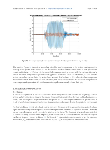
Figure 26. Non-compensated system and feed-forward system stability experiment with = 2 kg, = 1 Ns/m.
The result in Figure 26 shows that appending a feed-forward compensator to the system can improve the
stability of the system. At = 0 s to = 2.5 s, the machine is not in contact with humans, so both systems can
remain stable, but at = 2.5 s to = 6.5 s, where the human operator is in contact with the machine, it is clearly
shown that a non-compensated system faces an aggressive oscillation, but on the other hand, the feed-forward
system can reduce the oscillation by a significant amount, finally after = 6.5 s where the human operator
releases the contact, it shows that the feed-forward system can quickly eliminate the oscillation compared to a
non-compensated system that still oscillates even though humans already release their grip.
6. FEEDBACK COMPENSATION
6.1. Design
A feedback compensator or feedback controller is a control system that will measure the output signal of the
system and adjust the input signal to the system. Compared between the feed-forward and feedback compen-
sators, both will improve the performance of the system, but the advantage of the feedback system is that it
tends to have better robustness, which means it can maintain performance despite changes in the environment.
As shown in Figure 27, it is a feedback control system in this study, and we use acceleration as the feedback
signal because directly measuring absolute structure displacement is not easy in a practice situation. Therefore,
we use an accelerometer, which can easily be attached to the frame. The downside of an accelerometer is that
it cannot accurately measure a low frequency, but it can be used in this study because we consider only the
oscillation frequency range. In Figure 27, the block of represents the accelerometer to get the structure
2
acceleration, , from the structure displacement, , and is a compensator transfer function.