
Page 122 - Read Online
P. 122
Songthumjitti et al. Intell Robot 2023;3(3):306-36 I http://dx.doi.org/10.20517/ir.2023.20 Page 19 of 31
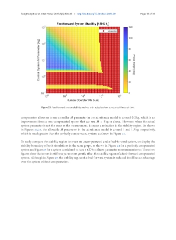
Figure 23. Feed-forward system stability analysis with actual system structure stiffness at 120%.
compensator allows us to use a smaller parameter in the admittance model to around 0.2 kg, which is an
improvement from a non-compensated system that can use = 5 kg or above. However, when the actual
system parameter is not the same as the measurement, it causes a reduction in the stability region. As shown
in Figures 22,23, the allowable parameter in the admittance model is around 1 and 1.5 kg, respectively,
which is much greater than the perfectly compensated system, as shown in Figure 21.
To easily compare the stability region between an uncompensated and a feed-forward system, we display the
stability boundary of both simulations in the same graph, as shown in Figure 24 for a perfectly compensated
systemandFigure25forasystemconsideredtohavea +20%stiffnessparametermeasurementerror. Thesetwo
figures show that errors in stiffness parameters greatly affect the stability region of a feed-forward compensated
system. Although in Figure 25, the stability region of a feed-forward system is reduced, it still has an advantage
over the system without compensation.