
Page 108 - Read Online
P. 108
Songthumjitti et al. Intell Robot 2023;3(3):306-36 I http://dx.doi.org/10.20517/ir.2023.20 Page 5 of 31
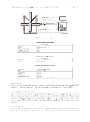
Figure 4. Experiment setup diagram.
Table 1. Force sensor specification
Force sensor
Manufacture Nitta
Model IFS-50M31A25-I25
Rated Input Force (XY) 100 N
Rated Input Force (Z) 200 N
Rated Input Torque (XYZ) 5 Nm
Table 2. Servo packs specification
Servo packs
Manufacture Yaskawa Electric Corporation
Model SGDV-2R8F01A
Table 3. AC servo motors specification
AC servo motors
Manufacture Yaskawa Electric Corporation
Model SGMJV-04ADA2C
Rated Output 400 W
Rated Torque 1.27 Nm
Rated Current 2.7 Arms
Rated Rotational Speed 3000 rpm
Encoder 20-bit serial encoder (incremental)
3.1.1. Force sensor
A Force sensor is a device used to measure the applied force and sends out digital data to the computer. In this
experiment, the force/torque sensor from Nitta was used, and its specifications are shown in Table 1.
3.1.2. Servo packs & AC servo motors
Servo packs and AC servo motors are devices that work together. Servo packs supply electrical power to an
AC servo motor, and the motor feeds feedback data from an encoder attached to its end to the servo pack,
which detects the current position and adjusts the electrical power so that the AC servo motors turn to the
correct position. Tables 2 and 3 show the specifications of the servo packs and AC servo motors used in the
experiment.
3.1.3. Linear sliders
The servo motor creates rotational motion, but in this experiment, the robot needs to move in horizontal and
vertical linear motion; therefore, linear sliders are used to convert rotational motion to linear motion. The