
Page 107 - Read Online
P. 107
Page 4 of 31 Songthumjitti et al. Intell Robot 2023;3(3):306-36 I http://dx.doi.org/10.20517/ir.2023.20
Figure 2. Human-machine interaction diagram.
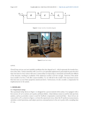
Figure 3. Experiment setup.
system.
Closed-loop systems can have instability problems that also depend on , which represents the transfer func-
tion of the robot. System instability will occur if it is not optimally implemented, particularly because the dead
time that exists in every system will cause a system delay in responding to commands and insufficient stiffness
of the structure, resulting in oscillation if the admittance model is not low enough. However, if the admit-
tance model is too low, it will affect maneuverability. So, we will derive the model of the experiment system
that takes into account these properties mentioned above. Furthermore, we also consider a compensator for
implementation in the system.
3. MODELING
3.1. Experiment setup
The experiment setup shown in Figure 3 is designed for a power-assisted robot system. It is equipped with a
forcesensor, ACservomotors, servopacks, andlinearsliders. Alaserdistancesensorisusedforonlyspectrum
analysis, and an acceleration sensor is used for feedback compensation mentioned later. These devices are
connected to a PC, as shown in Figure 4, to form the experiment setup, where the PC performs measurements,
calculates control operations, and outputs position command pulses to the servo packs with a sampling time
of 1 ms.