
Page 132 - Read Online
P. 132
Shi et al. Energy Mater 2023;3:300036 https://dx.doi.org/10.20517/energymater.2023.27 Page 9 of 14
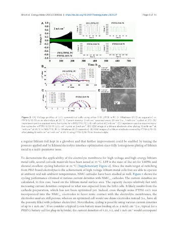
Figure 2. (A) Voltage profiles of Li/Li symmetrical cells using either 1 M LiTFSI in PC (+ Whatman GF/D as separator) or
-2 -2
PTFSI-5/10-70 as an electrolyte at 20 °C. Current density: 2 mA cm reversed every 30 min (i.e., 1 mAh cm cycled at 2C). (B)
-2
Impedance spectra acquired every five cycles for a 1M LiTFSI, PC Li/Li cell cycled at 2 mA cm . (C) Impedance spectra acquired every
-2 -2
five cycles for a PTFSI-5/10-70 Li/Li cell' cycled at 2 mA cm . (D) SEM image of a lithium electrode after plating 10 mAh cm at
-2
1 mA cm at 20 °C in 1M LiTFSI, PC (+ Whatman GF/D separator). (E) SEM images of a lithium electrode covered by PTFSI-4/10-70
-2 -2
after plating 10 mAh cm at 1 mA cm at 20 °C using PTFSI-5/10-70 as the electrolyte.
a regular lithium foil kept in a glovebox and that further improvement could be enabled by tuning the
pressure applied and by lithium/electrolyte interface optimization since fully homogenous plating of lithium
metal is a multi-parameter issue.
To demonstrate the applicability of the electrolyte membrane for high-voltage and high-energy lithium
metal cells, several cathode materials have been tested at 20 °C. LFP is the state-of-the-art for LMPBs and
showed excellent cycling behavior at 20 °C [Supplementary Figure 2]. Since the main target of switching
from PEO-based electrolytes is the achievement of high-voltage lithium metal cells that are able to operate
at ambient and sub-ambient temperatures, NMC cathodes have been studied as well. Figure 3 shows the
cycling performance obtained at various current densities with NMC cathodes. The current densities are
111
calculated, in this case, based on the lithium metal surface area. The capacity decays relatively fast with
increasing current densities compared to what was expected from the LiǁLi cells. It likely results from the
cathode preparation, which has not been optimized yet. Indeed, even though some PTFSI-10/5 was
incorporated into the NMC electrodes to favor ionic contact with the electrolyte membranes, the
111
electrodes used are still porous, whereas an optimized cell would use dense electrodes instead (i.e., have all
the porosity filled with polymer electrolyte). Nevertheless, cycling is possible using various current densities
-2
of up to 1 mA cm . If we consider a typical Li-ion battery mass loading of ca. 2 mAh cm (i.e., typical for a
-2
PHEV2 battery cell for plug-in hybrids), the current densities of 0.25, 0.5, and 1 mA cm would correspond
-2