
Page 131 - Read Online
P. 131
Page 8 of 14 Shi et al. Energy Mater 2023;3:300036 https://dx.doi.org/10.20517/energymater.2023.27
the one hand, the cell assembly process should not induce inhomogeneity for lithium transport pathways,
and the "softness" of the PTFSI-10/5-70 electrolyte is favorable in this regard. Indeed, hard contact points
would be likely to induce cracks in the passivation layer already present on the lithium foil following its
production by extrusion in dry air or Ar/CO and result in inhomogeneous lithium transport. On the other
2
hand, the resistance of the SEI should allow fast lithium transport and not be the limiting factor. In fact, it is
[33]
[32]
known from IL-electrolytes or ternary IL-plasticized polymer electrolytes that the SEI resistance often
represents a much higher hindrance to Li transport than that of the IL-free electrolyte, especially at ambient
+
and sub-ambient temperature.
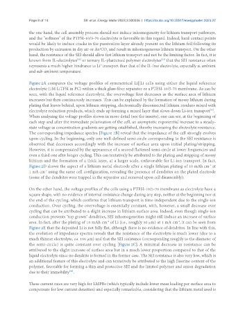
Figure 2A compares the voltage profiles of symmetrical Li||Li cells using either the liquid reference
electrolyte (1M LiTFSI in PC) within a thick glass fiber separator or a PTFSI-10/5-70 membrane. As can be
seen, with the liquid reference electrolyte, the overvoltage first decreases as the surface area of lithium
increases but then continuously increases. This can be explained by the formation of mossy lithium during
plating that leaves behind, upon lithium stripping, electronically disconnected lithium residues mixed with
electrolyte reduction products, which ends up forming a mixed layer that slows down Li-ion transport .
[34]
When analyzing the voltage profiles shown in more detail (see the inserts), one can see, at the beginning of
each step and after the immediate polarization of the cell, an asymptotic exponential increase to a steady-
state voltage as concentration gradients are getting established, thereby increasing the electrolyte resistance.
The corresponding impedance spectra [Figure 2B] reveal that the impedance of the cell strongly evolves
upon cycling. In the beginning, only one well-defined semi-circle corresponding to the SEI resistance is
observed that decreases accordingly with the increase of surface area upon initial plating/stripping.
However, it is compensated by the appearance of a second flattened semi-circle at lower frequencies and
even a third one after longer cycling. This can tentatively be attributed to the plating and stripping of mossy
lithium and the formation of a thick layer, at a larger scale, unfavorable for Li-ion transport. In fact,
Figure 2D shows the aspect of a lithium metal electrode after a single lithium plating of 10 mAh cm at
-2
1 mA cm using the same cell configuration, revealing the presence of dendrites on the plated electrode
-2
(some of the dendrites were trapped in the separator and removed upon cell disassembly).
On the other hand, the voltage profiles of the cells using a PTFSI-10/5-70 membrane as electrolyte have a
square shape, with no evidence of internal resistance change during any step, neither at the beginning nor at
the end of the cycling, which confirms that lithium transport is time-independent due to the single-ion
conduction. Over cycling, the overvoltage is essentially constant, with, however, a small decrease over
cycling that can be attributed to a slight increase in lithium surface area. Indeed, even though single-ion
conduction prevents "top grown" dendrites, SEI inhomogeneities might still induce an increase of surface
area. In fact, after the plating of 10 mAh cm of Li (i.e., roughly 50 µm) at 1 mA cm , it can be seen from
-2
-2
Figure 2E that the deposited Li is not fully flat, although there is no evidence of dendrites. In line with this,
the evolution of impedance spectra reveals that the resistance of the electrolyte is much lower (due to a
much thinner electrolyte, ca. 100 µm) and that the SEI resistance (corresponding roughly to the diameter of
the semi-circle) is quite constant over cycling [Figure 2C]. A minimal decrease in resistance can be
attributed to the slight increase of surface area but in a much lower proportion compared to that of the
liquid electrolyte since no dendrite is formed in the former case. The SEI resistance is also very low, which is
an additional feature of this electrolyte and can tentatively be attributed to the high fluorine content of the
polymer, favorable for forming a thin and protective SEI and the limited polymer and anion degradation
due to their immobility .
[35]
These current rates are very high for LMPBs (which typically include lower mass loading per surface area to
compensate for low current densities) and especially remarkable, considering that the lithium metal used is