
Page 176 - Read Online
P. 176
Page 8 of 16 Li et al. Energy Mater 2023;3:300021 https://dx.doi.org/10.20517/energymater.2023.09
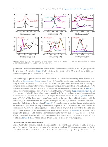
Figure 2. High-resolution XPS spectra of (A) C 1s, (B) N 1s, and (C) Fe 2p in the FePc and FePc/Se@NiFe. High-resolution XPS spectra
of (D) Ni 2p, (E) Se 3d, (F) O 1s, and (F) O 1s for FePc/Se@NiFe.
-
spectrum of FePc/Se@NiFe supports the results inferred from the Raman spectra as the OH groups indicate
the presence of NiFe(OH) [Figure 2F]. In addition, the strong peak of O 1s spectrum at 532.3 eV is
X
corresponding to physically adsorbed H O molecular.
2
The morphology of precursors and FePc/Se@NiFe catalyst were characterized by SEM techniques. As
described in Supplementary Figure 3A and B, pure FePc exhibits a highly aggregated granular state with a
rough surface, in contrast to the manufactured NiFe-LDH precursors, which are formed of irregular
polygonal thin nanosheets with very smooth surfaces. Compared with pure NiFe-LDH and FePc, the FePc/
Se@NiFe catalyst exhibited a lot of irregular nanoparticles homogeneously scattered on carbon [Figure 3A].
Similar observations are made on Se@NiFe, FePc/Se@Ni, and FePc/Se@Fe [Supplementary Figure 3C-E].
The shape of the NiFe-LDH nanosheet changed significantly from nanosheets to irregular nanoparticles,
indicating that excessive selenization caused damage to the nanosheets structure . In Figure 3B, the TEM
[57]
image of FePc/Se@NiFe also reveals a mass of nanoparticles in the carbon layer, which is consistent with the
SEM findings. HRTEM shows that the tri-phase nanocrystalline coating exhibits an amorphous structure, as
marked on the left side of the white lines [Figure 3C]. A crystalline-amorphous interface growth is beneficial
for the OER catalysis, which not only facilitates the adsorption of OH* intermediates but also accelerates the
[58]
formation of OOH* . The lattice spacings of 0.269 and 0.266 nm, which correspond to the (-312) and
(-402) crystal planes of Ni Se , respectively, can be distinctly visualized in Figure 3D. In addition, lattice
3
4
fringes with spacings of 0.245 nm and 0.469 nm attributed to the (400) plane of Fe O and the (11-1) plane
4
3
of Se are also clearly displayed. This result is the same as the previous XRD. TEM mapping images of FePc/
Se@NiFe in Figure 3E-K show the elements of C, N, O, Fe, Ni, and Se are evenly dispersed.
ORR and OER catalytic performance
The Fe-N structure possessed by FePc is considered to be the catalytically active site of ORR. In order to
4
judge the oxygen reduction performance of the prepared catalysts, CV scans were carried out in N -
2
saturated and O -saturated 0.1M KOH electrolyte solutions, respectively. As presented in
2