
Page 174 - Read Online
P. 174
Page 6 of 16 Li et al. Energy Mater 2023;3:300021 https://dx.doi.org/10.20517/energymater.2023.09
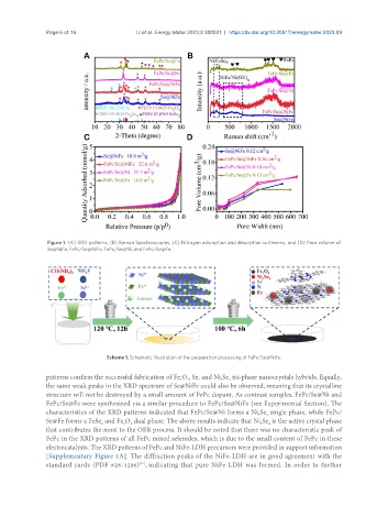
Figure 1. (A) XRD patterns, (B) Raman Spectroscopies, (C) Nitrogen adsorption and desorption isotherms, and (D) Pore volume of
Se@NiFe, FePc/Se@NiFe, FePc/Se@Ni, and FePc/Se@Fe.
Scheme 1. Schematic illustration of the preparation processing of FePc/Se@NiFe.
patterns confirm the successful fabrication of Fe O , Se, and Ni Se tri-phase nanocrystals hybrids. Equally,
4
3
4
3
the same weak peaks in the XRD spectrum of Se@NiFe could also be observed, meaning that its crystalline
structure will not be destroyed by a small amount of FePc dopant. As contrast samples, FePc/Se@Ni and
FePc/Se@Fe were synthesized via a similar procedure to FePc/Se@NiFe (see Experimental Section). The
characteristics of the XRD patterns indicated that FePc/Se@Ni forms a Ni Se single phase, while FePc/
4
3
Se@Fe forms a FeSe and Fe O dual phase. The above results indicate that Ni Se is the active crystal phase
4
3
3
2
4
that contributes the most to the OER process. It should be noted that there was no characteristic peak of
FePc in the XRD patterns of all FePc mixed selenides, which is due to the small content of FePc in these
electrocatalysts. The XRD patterns of FePc and NiFe-LDH precursors were provided in support information
[Supplementary Figure 1A]. The diffraction peaks of the NiFe-LDH are in good agreement with the
[47]
standard cards (PDF #26-1286) , indicating that pure NiFe-LDH was formed. In order to further