
Page 71 - Read Online
P. 71
Huang et al. Complex Eng Syst 2023;3:2 I http://dx.doi.org/10.20517/ces.2022.43 Page 15 of 20
Table 1. ETRS89 coordinate System
Name Value
EPSG number EPSG:25832
Prime meridian Greenwich
Earth’s ellipsoid GRS 1980 (long axis: 6,378,137 m, flat rate: 298.257,222)
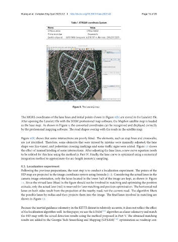
Figure 9. The lanelet2 map.
The MGRS coordinates of the lane lines and initial points shown in Figure 8(b) are stored in the Lanelet2 file.
After opening the Lanelet2 file with the JOSM professional map software, the Mapbox satellite map is loaded
as the base map. As shown in Figure 9, the converted coordinates can be recognized and displayed correctly
by the professional mapping software. The road shapes overlap with the roads in the satellite map.
Figure 8(b) shows that some intersections are poorly fitted. The elements, such as stop lines and crosswalks,
are not identified. Therefore, some elements that were missed by mistake were manually adjusted, the lane
shape was fine-tuned, and pedestrian crossing markings and some traffic signs were added. Figure 10 shows
the effect of manual labeling of some intersections. After adjusting the lane lines, a new curve equation needs
to be refitted for this lane using the method in Part IV. Finally, the lane curve is optimized using a numerical
integration method to approximate the arc-length isometric sampling.
6.3. Localization experiment
Following the previous preparations, the next step is to conduct a localization experiment. The points of the
HD map are projected in the image coordinate system using formula (11). Considering the actual lanes in the
camera image orientation, only the lanes located in the lower half of the image are kept, as shown in Figure
11. Since the virtual lane (blue) in the figure should not be involved in matching and optimizing the position
attitude, only the actual lane (red) is reserved for lane matching and position optimization. The horizontal red
lanes on both sides result from the projection of the nearby road, not the current road. The algorithm filters
the possible lanes by radius and then projects them into the image. The final lanes involved in matching are
shown in Figure 12.
Because the inertial guidance odometry in the KITTI dataset is relatively accurate, it does not reflect the effect
ofthelocalizationalgorithmwell. Inthispaper, weusetheLOAM [22] algorithmasalaserodometryandmatch
the HD map with the actual detection results using the method proposed in Part V. The obtained matching
results are added to the Georgia Tech Smoothing and Mapping (GTSAM) [40] optimization as roadmap con-