
Page 23 - Read Online
P. 23
Ying et al. Microstructures 2023;3:2023018 https://dx.doi.org/10.20517/microstructures.2022.47 Page 3 of 15
MATERIALS AND METHODS
Sample preparation and fluxing treatment
[(FeNiCo) Cr ] B (x = 12, 15, 17) ingots were prepared by vacuum induction heating using pure
0.15 100-x x
0.85
elements (purity > 99.95 wt.%). Then, the alloy ingots were remelted at least five times under a high-purity
Ti-gettered argon atmosphere in a water-cooled copper crucible; the ingots were flipped each time to
improve the chemical homogeneity. After that, the alloy ingots were transferred into molten B O and
2
3
underwent fluxing treatment for 2 h at 1,473 K in a dry-cleaned fused silica tube with inner and outer
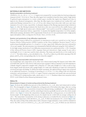
diameters of 16 and 19 mm, respectively. A schematic diagram of the fluxing experiment setup is shown in
Figure 1A. After the fluxing treatment, the fused silica tube was removed from the muffle furnace and
[28]
cooled in air. A high-speed camera and a thermocouple were used to record the cooling process of the
system and the temperature history, respectively. To measure the liquidus temperature (T ) of the samples,
L
differential scanning calorimeter (DSC) experiments (Netzsch 404 F3) were performed under a high-purity
argon atmosphere, with a cooling rate of 20 K min from 1,500 K to 300 K.
-1
Neutron and synchrotron X-ray diffraction experiments
Time-of-flight neutron diffraction experiments in transmission mode were carried out on the General
Purpose Powder Diffractometer (GPPD) beamline at the China Spallation Neutron Source , with a
[29]
neutron beam bandwidth and size of 4.5 Å and 40 × 20 mm, respectively. Diffraction data were collected for
2 h on each sample. The microstructure was determined by Rietveld refinement using the GSAS software .
[30]
In situ high-energy synchrotron X-ray diffraction measurements were performed at the 11-ID-C beamline
of the Advanced Photon Source (APS, Argonne National Laboratory). High-energy X-rays with a
wavelength of 0.01173 nm were used for data collection. The strain rate used in the in situ tensile test is
4 × 10 s . The lattice strain ε was calculated as (d - d° )/(d° ), where d is the lattice spacing of the hkl
-4 -1
hkl
hkl
hkl
hkl
hkl
planes, and d° is the corresponding value for the stress-free sample .
[6]
hkl
Morphology characterization and mechanical tests
The morphology and composition of the alloy were characterized using FEI Quanta 250F SEM, JSM-
IT500HR SEM, and FEI Talos F200X TEM microscopes equipped with an attached X-ray EDS instrument.
Cylinder-shaped compressive samples with a diameter of 3 mm and a height of 4.5 mm, as well as dog-
bone-shaped tensile specimens with a gauge length of 10 mm and a thickness of 1mm were fabricated by
electrical discharge machining. To obtain the tensile specimens, the spherical fluxed ingots were subjected
to an additional treatment, consisting of annealing at 1,273 K for 10 h, hot rolling (with 80% thickness
reduction), and annealing at 1,273 K for 10 h again. Uniaxial compressive and tensile tests were performed
on a UTM4304GD testing machine with a strain rate of 1 × 10 s . Hardness values were measured with a
-3 -1
HVST-1000Z (Deka Precision Measuring Instrument) tester.
RESULTS
Measurement of degree of undercooling achieved by fluxing treatment
Figure 1B shows the solidification process of the [(FeNiCo) Cr ] B alloy melt immersed in molten
0.15 83 17
0.85
B O . The photographs in Figure 1B display the cooling process of the molten alloy ingot. After air-cooling
3
2
[31]
for 35 s 14 ms, recalescence occurred due to latent heat released during crystallization . The crystallization
occurred on the sample surface, and the crystal/liquid interface gradually moved across the whole sample
within 5 ms. Figure 1C shows the temperature changes during the cooling process, as recorded by the
thermocouple. At the beginning of the process, the sample was air-cooled with an average cooling rate of
-1
2 K s . The temperature increased by 135 K during recalescence, as marked by the red arrow in Figure 1C.
The liquidus temperature of the [(FeNiCo) Cr ] B N-HEA was measured to be 1,350 K [Figure 1D].
0.85
0.15 83 17
Thus, the undercooling of the molten alloys with a diameter of approximately 13 mm could be estimated at
385 K. The DSC curves of [(FeNiCo) Cr ] B and [(FeNiCo) Cr ] B N-HEAs are also shown in
0.85
0.15 85 15
0.15 88 12
0.85