
Page 143 - Read Online
P. 143
Page 4 of 31 Lee et al. Soft Sci 2024;4:38 https://dx.doi.org/10.20517/ss.2024.36
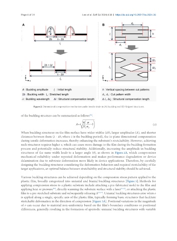
Figure 2. Dimensional compensation mechanism under tensile strain in (A) buckling and (B) Kirigami structures.
[32]
of the buckling structure can be summarized as follows .
(2)
When buckling structures on the film surface have wider widths (2b), larger amplitudes (A), and shorter
distances between them (λ - 2b, where λ is the buckling period), the in-plane dimensional compensation
during tensile deformation increases, thereby enhancing the substrate’s stretchability. However, achieving
such structures requires higher σ, which can cause more damage to the film during the buckling formation
process and potentially reduce structural stability. Additionally, increasing the amplitude in buckling
structures of the same width leads to a larger angle (θ), as shown in Figure 2A, which compromises
mechanical reliability under repeated deformation and makes performance degradation or device
delamination due to substrate deformation more likely in device applications. Therefore, by carefully
designing the buckling structures considering the deformation behaviors and required stretchability of the
target applications, an optimal balance between stretchability and structural stability should be achieved.
Various buckling structures can be achieved depending on the compression stress pattern applied to the
plastic film, broadly categorized into uniaxial and biaxial buckling structures [Figure 3]. Methods for
applying compression stress to a plastic substrate include attaching a pre-fabricated mold to the film and
[40]
applying heat or pressure , directly scanning the substrate surface with a laser [41,42] , or attaching the plastic
film to a pre-stretched substrate and subsequently releasing it [43,44] . Uniaxial buckling structures arise when σ
is applied along a single, specific axis of the plastic film, typically forming basic structures that facilitate
stretchable deformation in the direction of compression [Figure 3A]. Positional variations in the magnitude
of σ can occur due to material non-uniformity based on the film’s boundary conditions or positional
differences, generally resulting in the formation of aperiodic uniaxial buckling structures with variable