
Page 120 - Read Online
P. 120
Keum et al. Soft Sci 2024;4:34 https://dx.doi.org/10.20517/ss.2024.26 Page 13 of 32
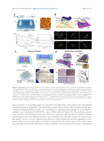
Figure 7. Stretchable semiconducting films and TFTs based on organic semiconductors. (A) (i) Schematic illustration of nanofiber-
structured DPPT-TT OTFTs and atomic force microscope image of the semiconducting layer. (ii) Electrical characteristics of nanofiber-
[71]
structured OTFT . Copyright 2023, Wiley-VCH; (B) Structure of stretchable AMOLEC array and photographs of AMOLEC display
[61]
pixels . Copyright 2020, Springer Nature; (C) Concept of inserting a stress-relief interlayer between the semiconductor and
substrate [87] . Copyright 2023, Springer Nature; (D) Schematic illustration and optical microscope images of a micro-wrinkle pattern
semiconductor film and the electrical performance of OTFTs [91] . Copyright 2021, Wiley-VCH. TFT: Thin-film transistor; DPPT-TT: poly-
[2,5-bis(2-octyldodecyl)−3,6-di(thiophen-2-yl) pyrrolo [3,4-c]pyrrole-1,4(2H,5H)-dionel-alt-thieno [3,2-b]thiophene]; OTFT: organic
thin film transistor; AMOLEC: AM-driven organic light-emitting electrochemical cell.
films in the form of a mesh-like pattern to control the stress distribution and to improve the stretchability
and charge transport properties . The stretchable polymer semiconductor film was fabricated by spin-
[91]
coating π-conjugated polymer, poly[2,5-(2-octyldodecyl)-3,6-diketopyrrolopyrrole-alt-5,5-(2,5-di(thien-2-
yl)thieno [3,2-b]-thiophene)] (DPP-DTT), onto a PDMS substrate [Figure 7D]. The mesh-like patterns
were formed by controlling the ultraviolet (UV)/ozone treatment time and elastic modulus of PDMS
(optimizing the ratio of the PDMS prepolymer and crosslinker) before the spin coating. The formed mesh-
like pattern consists of vacant regions in the deep part of the wrinkles and polymer aggregated crystal
regions where the percolation paths are formed. It is reported that the vacant regions of the mesh wrinkle
are responsible for the stress distribution which contributes to preventing the performance degradation