
Page 17 - Read Online
P. 17
Page 6 of 12 Jan et al. Soft Sci 2024;4:10 https://dx.doi.org/10.20517/ss.2023.54
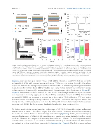
Figure 2. Cyclic performance evaluation of LF-TENG. (A) Working mechanism of LF-TENGs based on CS modes; (B) Representative
voltage output of LF-TENGs based on CS modes; (C) Schematic diagram of mechanical tapping device used for the cyclic performance
evaluation of LF-TENGs. The top layer (PTFE) is attached to a glass substrate fixed on the movable clamp, and the bottom layer
(PMMA) is affixed to the vacuum chuck over a load-measuring unit. The voltage output was recorded by an oscilloscope; (D) Voltage
output of LF-TENG as a function of separation gap (d = 2, 3, 4, and 5 mm) when the tapping frequency and force are fixed at 4 Hz and
6.3 N; (E) Voltage output of LF-TENG as a function of tapping frequency (1, 2, 3, and 4 Hz) at d = 5 mm and F = 6.3 N. CS: Contact-
separation; LF-TENG: laminated flexible-triboelectric nanogenerator; PMMA: polymethyl methacrylate; PTFE: polytetrafluoroethylene.
Figure 3A compares the open circuit voltage of LF-TENG, which has an ITO/Cu bottom electrode
embedded in PMMA, with a control sample (without an ITO layer on the bottom electrode). The voltage
output was obtained at a tapping frequency of 4 Hz and force of 6.3 N, while the separation gap was fixed as
5 mm. It was observed that the LF-TENG with ITO layer on the bottom electrode showed an 85.7% rise in
voltage output. A bridge rectifier was used to convert alternating current to direct current [Figure 3B].
Figure 3C illustrates the rectified current of LF-TENG and the control sample. For both samples, the current
was measured by manually tapping the top layer (PTFE) on the bottom layer (PMMA). The rectified
current of LF-TENG was measured to be 400% higher than that of TENG without an ITO layer on the
bottom electrode. The ability of charge collection of the bottom Cu electrode was improved when a thin
layer (~440 nm) of ITO was sputtered on it since the ITO can fill in the cracks formed on the Cu electrode
deposited on O-PDMS, thereby improving the electrical conductivity from 8.70 to 75.8 S/m.
To further investigate the energy harvesting performance of LF-TENG, the rectified voltage and current
were measured at various Ohmic loads ranging from 1 kΩ to 2 GΩ. The voltage increased with increasing
load while the current decreased due to the high ohmic losses [Figure 3D]. At first, the current slightly
decreased in the range of 1 kΩ to 1 MΩ since the charge transfer was rather similar to the short circuit
condition. However, the charge transfers notably decreased from 1 MΩ to 2 GΩ, resulting in diminished
current output. The output of LF-TENG is close to the current open circuit condition . The rectified
[12]
current data at various ohmic loads is presented in Supplementary Figure 5. The electronic devices have