
Page 16 - Read Online
P. 16
Jan et al. Soft Sci 2024;4:10 https://dx.doi.org/10.20517/ss.2023.54 Page 5 of 12
On the other hand, for tribo-negative layers, a 920 nm thick Cu electrode was sputtered on the top of a
100 μm thick PTFE film. After pasting the tin-plated copper tape onto the Cu electrode, the surface was
coated by spin coating 100 μm thick PDMS, which was cured at 65 °C for 2.5 h. Finally, the LF-TENG, as
shown in Figure 1A, was assembled to test the cyclic performance. It was encapsulated in two pieces of (30
by 40 mm ) 0.3 mm thick PDMS to create a sensor for monitoring human motion. Before encapsulation, a 1
2
mm thick acrylic spacer was inserted along both edges to form a gap between the PTFE and PMMA
surfaces. The encapsulated LF-TENG is represented as an E-TENG hereafter.
RESULTS AND DISCUSSION
Working mechanism and cyclic performance
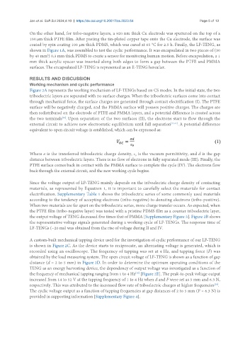
Figure 2A represents the working mechanism of LF-TENGs based on CS modes. In the initial state, the two
triboelectric layers are separated with no surface charges. When the triboelectric surfaces come into contact
through mechanical force, the surface charges are generated through contact electrification (I). The PTFE
surface will be negatively charged, and the PMMA surface will possess positive charges. The charges are
then redistributed on the electrode of PTFE and PMMA layers, and a potential difference is created across
the two terminals . Upon separation of the two surfaces (II), the electrons start to flow through the
[12]
external circuit to achieve new electrostatic equilibrium until full separation [11,37] . A potential difference
equivalent to open circuit voltage is established, which can be expressed as:
Where σ is the transferred triboelectric charge density, ε is the vacuum permittivity, and d is the gap
0
distance between triboelectric layers. There is no flow of electrons in fully separated mode (III). Finally, the
PTFE surface comes back in contact with the PMMA surface to complete the cycle (IV). The electrons flow
back through the external circuit, and the new working cycle begins.
Since the voltage output of LF-TENG mainly depends on the triboelectric charge density of contacting
materials, as represented by Equation 1, it is important to carefully select the materials for contact
electrification. Supplementary Table 1 shows the triboelectric series of some commonly used materials
according to the tendency of accepting electrons (tribo-negative) to donating electrons (tribo-positive).
When two materials are far apart on the triboelectric series, more charge transfer occurs. As expected, when
the PTFE film (tribo-negative layer) was tested with a pristine PDMS film as a counter triboelectric layer,
the output voltage of TENG decreased five times that of PMMA [Supplementary Figure 3]. Figure 2B shows
the representative voltage signals generated during a working cycle of LF-TENGs. The response time of
LF-TENGs (~20 ms) was obtained from the rise of voltage during II and IV.
A custom-built mechanical tapping device used for the investigation of cyclic performance of our LF-TENG
is shown in Figure 2C. As the device starts to reciprocate, an alternating voltage is generated, which is
recorded using an oscilloscope. The frequency of tapping was set at 4 Hz, and tapping force (F) was
obtained by the load measuring system. The open circuit voltage of LF-TENG is shown as a function of gap
distance (d = 2 to 5 mm) in Figure 2D. In order to determine the optimum operating conditions of the
TENG as an energy harvesting device, the dependency of output voltage was investigated as a function of
the frequency of mechanical tapping ranging from 1 to 4 Hz [Figure 2E]. The peak-to-peak voltage output
[38]
increased from 14 to 52 V at the tapping frequency of 1 to 4 Hz when d and F were set as 5 mm and 6.3 N,
respectively. This was attributed to the increased flow rate of triboelectric charges at higher frequencies .
[39]
The cyclic voltage output as a function of tapping frequencies at gap distances of 2 to 5 mm (F = 6.3 N) is
provided in supporting information [Supplementary Figure 4].