
Page 182 - Read Online
P. 182
Bhandari et al. Metacarpal angulations
dissected to harvest 118 metacarpal bones. Two hands
A
had one digit missing. The bones were dissected free
from the surrounding soft tissue.
After harvesting the metacarpal, a true lateral view of
each metacarpal was taken using fluoroscopy. The
pictures were analysed by Image J software (National
Institute of Health, Bethesda, Maryland, USA).
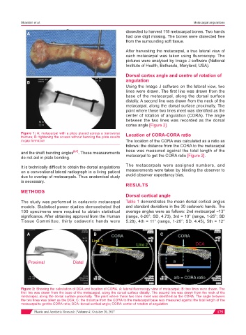
Dorsal cortex angle and centre of rotation of
B angulation
Using the Image J software on the lateral view, two
lines were drawn. The first line was drawn from the
base of the metacarpal, along the dorsal surface
distally. A second line was drawn from the neck of the
metacarpal, along the dorsal surface proximally. The
point where these two lines meet was identified as the
center of rotation of angulation (CORA). The angle
between the two lines was recorded as the dorsal
cortex angle [Figure 2].
Figure 1: A: metacarpal with a plate placed across a transverse Location of CORA-CORA ratio
fracture; B: tightening the screws without bending the plate results
in gap formation The location of the CORA was calculated as a ratio as
follows: the distance from the CORA to the metacarpal
and the shaft bending angles [4,5] . These measurements base was measured against the total length of the
do not aid in plate bending. metacarpal to get the CORA ratio [Figure 2].
It is technically difficult to obtain the dorsal angulations The metacarpals were assigned numbers, and
on a conventional lateral radiograph in a living patient measurements were taken by blinding the observer to
due to overlap of metacarpals. Thus anatomical study avoid observer expectancy bias.
is necessary.
RESULTS
METHODS
Dorsal cortical angle
The study was performed in cadaveric metacarpal Table 1 demonstrates the mean dorsal cortical angles
models. Statistical power studies demonstrated that and standard deviations in the 30 cadaveric hands. The
100 specimens were required to obtain statistical average angles were as follows: 2nd metacarpal =13°
significance. After obtaining approval from the Human (range, 6-26°; SD, 4.73), 3rd = 10° (range, 1-25°; SD
Tissue Committee, thirty cadaveric hands were 5.28), 4th = 11° (range, 1-20°; SD, 4.45), 5th = 12°
A B CORA C CORA
Line 1
Line 2 DCA
Proximal Distal a
b
a/b = CORA ratio
Figure 2: Showing the calculation of DCA and location of CORA. A: lateral fluoroscopy view of metacarpal; B: two lines were drawn. The
first line was drawn from the base of the metacarpal, along the dorsal surface distally. The second line was drawn from the neck of the
metacarpal, along the dorsal surface proximally. The point where these two lines meet was identified as the CORA. The angle between
the two lines was taken as the DCA; C: the distance from the CORA to the metacarpal base was measured against the total length of the
metacarpal to get the CORA ratio; DCA: dorsal cortical angle; CORA: center of rotation of angulation
Plastic and Aesthetic Research ¦ Volume 4 ¦ October 20, 2017 175