
Page 51 - Read Online
P. 51
Kitahama et al. PLPED with EMG monitoring under general anesthesia
operative step. To make the tunnels under the PLL, endoscope in the outer sheath removes the bubbles
it is necessary to repeat 2-3 times of hand-down and provides clear visualization. After decompression,
technique. When a piece of the fragment becomes the working sheath was carefully removed, and skin
[8]
visible from hiatus of the annulus fibrosus, it is possible was closed with a single suture.
to remove the fragment by an endoscope inserted from
a horizontal direction. Although bleeding can cloud the Optional advanced procedures
view during discectomy and fragmentectomy, pin point Partial facetectomy [9,10] and pediculotomy were
[11]
and short time (within 6 s) bipolar coagulation using a performed for total removal of the foraminal type LDH.
bipolar radio-frequency electrode system (Elliquence, For these techniques, an electrical high speed drill
Baldwin, NY, USA) allows hemostasis to be achieved. Primado 2 with Super Slim Attachment 200 (NSK-
®
®
Microbubbles during operative manipulation can also Nakanishi medical, Tochigi, Japan) was utilized. For the
cloud the view. Upward and downward motion of the medial type of LDH, beak forceps were used for sharp
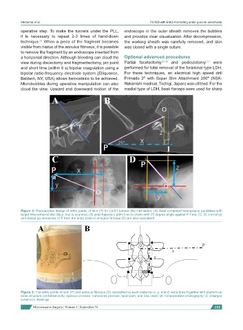
Figure 2: Preoperative design of entry points of skin (P) for L5/S1 lumbar disc herniation. (A) Axial computed tomography paralleled with
target intervertebral disc (blue line) is scanned; (B) axial trajectory (pink line) is drawn with 25 degree angle against P-I line; (C, D) cranial (y)
and dorsal (z) deviations of P from the entry point of annulus fibrosus (O) are also calculated
Figure 3: The entry points of skin (P) and annulus fibrosus (O) calculated by each distance (x, y, and z) were draw together with anatomical
bone structure (vertebral body, spinous process, transverse process, facet joint, and iliac crest) (A: intraoperative photography; B: enlarged
schematic drawing)
Mini-invasive Surgery ¦ Volume 1 ¦ September 30 111