
Page 98 - Read Online
P. 98
Mai et al. Intell Robot 2023;3(4):466-84 I http://dx.doi.org/10.20517/ir.2023.37 Page 5 of 19
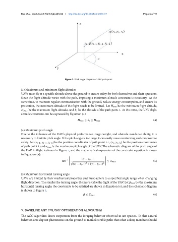
Figure 2. Pitch angle diagram of UAV path point.
(3) Maximum and minimum flight altitudes
UAVs must fly at a specific altitude above the ground to ensure safety for both themselves and their operators.
Since the flight altitude varies with the path, imposing a minimum altitude constraint is necessary. At the
same time, to maintain regular communication with the ground, reduce energy consumption, and ensure its
protection, the maximum altitude of the flight needs to be limited. Let be the minimum flight altitude,
be the maximum flight altitude, and ℎ be the altitude of the path point i. At this time, the UAV flight
altitude constraint can be expressed by Equation (4):
≤ ℎ ≤ (4)
(4) Maximum pitch angle
Due to the influence of the UAV’s physical performance, cargo weight, and obstacle avoidance ability, it is
necessary to limit its pitch angle. If the pitch angle is too large, it can easily cause overturning and compromise
safety. Let ( −1 , −1 , −1 ) be the position coordinates of path point i-1, ( , , ) be the position coordinates
of path point i, and is the maximum pitch angle of the UAV. The schematic diagram of the pitch angle of
the UAV in flight is shown in Figure 2, and the mathematical expression of the constraint equation is shown
in Equation (5):
[ ]
| − −1 |
−1
tan √ ≤ (5)
2 2
( − −1 ) + ( − −1 )
(5) Maximum horizontal turning angle
UAVs are limited by their mechanical properties and must adhere to a specified angle range when changing
flight direction. The smaller the turning angle, the more stable the flight of the UAV. Let be the maximum
horizontal turning angle; the constraints to be satisfied are shown in Equation (6), and the schematic diagram
is shown in Figure 3.
(6)
≤
3. BASELINE ANT COLONY OPTIMIZATION ALGORITHM
The ACO algorithm draws inspiration from the foraging behavior observed in ant species. In this natural
behavior, ants deposit pheromones on the ground to mark favorable paths that other colony members should