
Page 97 - Read Online
P. 97
Page 4 of 19 Mai et al. Intell Robot 2023;3(4):466-84 I http://dx.doi.org/10.20517/ir.2023.37
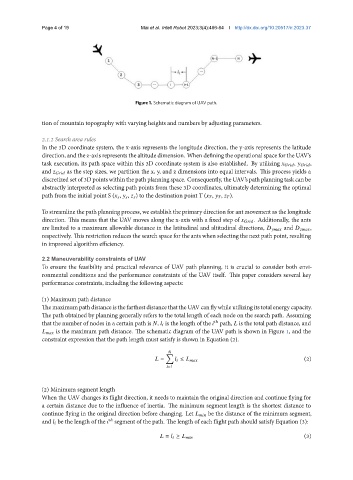
Figure 1. Schematic diagram of UAV path.
tion of mountain topography with varying heights and numbers by adjusting parameters.
2.1.2 Search area rules
In the 3D coordinate system, the x-axis represents the longitude direction, the y-axis represents the latitude
direction, and the z-axis represents the altitude dimension. When defining the operational space for the UAV’s
task execution, its path space within this 3D coordinate system is also established. By utilizing , ,
and as the step sizes, we partition the x, y, and z dimensions into equal intervals. This process yields a
discretizedsetof3D pointswithin thepath planningspace. Consequently, the UAV’spath planningtaskcan be
abstractly interpreted as selecting path points from these 3D coordinates, ultimately determining the optimal
path from the initial point S ( , , ) to the destination point T ( , , ).
To streamline the path planning process, we establish the primary direction for ant movement as the longitude
direction. This means that the UAV moves along the x-axis with a fixed step of . Additionally, the ants
are limited to a maximum allowable distance in the latitudinal and altitudinal directions, and ,
respectively. This restriction reduces the search space for the ants when selecting the next path point, resulting
in improved algorithm efficiency.
2.2 Maneuverability constraints of UAV
To ensure the feasibility and practical relevance of UAV path planning, it is crucial to consider both envi-
ronmental conditions and the performance constraints of the UAV itself. This paper considers several key
performance constraints, including the following aspects:
(1) Maximum path distance
ThemaximumpathdistanceisthefarthestdistancethattheUAVcanflywhileutilizingitstotalenergycapacity.
The path obtained by planning generally refers to the total length of each node on the search path. Assuming
ℎ
that the number of nodes in a certain path is , is the length of the path, is the total path distance, and
is the maximum path distance. The schematic diagram of the UAV path is shown in Figure 1, and the
constraint expression that the path length must satisfy is shown in Equation (2).
∑
= ≤ (2)
=1
(2) Minimum segment length
When the UAV changes its flight direction, it needs to maintain the original direction and continue flying for
a certain distance due to the influence of inertia. The minimum segment length is the shortest distance to
continue flying in the original direction before changing. Let be the distance of the minimum segment,
and be the length of the segment of the path. The length of each flight path should satisfy Equation (3):
ℎ
(3)
= ≥ 