
Page 142 - Read Online
P. 142
Page 427 Chen et al. Intell Robot 2023;3:420-35 https://dx.doi.org/10.20517/ir.2023.24
Figure 8. Structure of the signal amplifier circuit. (A) Darlington transistor; (B) Signal amplifier board.
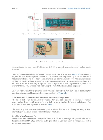
Figure 9. Tactile display system and tactile actuators.
communication and outputs the PWM current via GPIO to properly control the motors and the tactile
actuators.
The SMA actuators and vibration motors are stitched into the glove, as shown in Figure 10A. In this tactile
display, the SMA actuators present various vibratory stimuli with frequencies up to 300 Hz, which is a
unique characteristic when compared with conventional vibration motors. Two vibration motors are
stitched in the index and ring fingers of the glove, respectively, and four SMA actuators are stitched in the
back side of the hand. By arranging eight actuators in a glove, various tactile patterns are presented by
selectively driving SMA actuators with controlled pulse currents that have different frequencies.
All of the control circuits were put into a square box with a size of 16 cm × 10 cm × 5 cm so that during the
experiment, the user could carry the whole system, as shown in Figure 10B.
2.9. Presentation of object location and distance through tactile patterns
The recognized object information is presented through tactile patterns. We consider intuitive
understanding through tactile sensation by empirically trying to associate the location and distance of an
object with different tactile patterns, as shown in Table 1.
The reason why the actuators are woven into gloves to present the vibrations is that a glove is easy to wear,
and our fingers and hands are also sensitive to minute vibrations.
2.10. Use of two Raspberry Pis
In this system, two Raspberry Pis are employed, one for the control of the recognition part and the other for
the control of the SMA actuators for the tactile presentation. Communication occurs using the socket
communication protocol.