
Page 141 - Read Online
P. 141
Chen et al. Intell Robot 2023;3:420-35 https://dx.doi.org/10.20517/ir.2023.24 Page 426
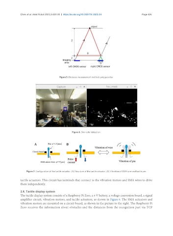
Figure 5. Distance measurement method using parallax.
Figure 6. Skin color detection.
Figure 7. Configuration of the tactile actuator. (A) Structure of the tactile actuator; (B) Vibration of SMA wire and tactile pin.
tactile actuators. This circuit has terminals that connect to the vibration motors and SMA wires to drive
them independently.
2.8. Tactile display system
The tactile display system consists of a Raspberry Pi Zero, a 9 V battery, a voltage conversion board, a signal
amplifier circuit, vibration motors, and tactile actuators, as shown in Figure 9. The SMA actuators and
vibration motors are mounted on a circuit board, as shown in the picture to the right. The Raspberry Pi
Zero receives the information about obstacles and the distances from the recognition part via TCP