
Page 130 - Read Online
P. 130
Songthumjitti et al. Intell Robot 2023;3(3):306-36 I http://dx.doi.org/10.20517/ir.2023.20 Page 27 of 31
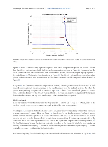
Figure 34. Stability region boundary comparison between a non-compensated system, a feed-forward system, and a feedback system at
100% .
Figure 31 shows that the stability region is improved over a non-compensated system, but it is still smaller
than the stability region achieved with feed-forward compensation, as shown in Figure 21. However, when the
actual system structure stiffness decreases from measurement by 20%, the stability region slightly expands, as
shown in Figure 32. On the other hand, as shown in Figure 33, the stability region still decreases when actual
system stiffness increases from measurement by 20%, but it can remain stable compared to feed-forward in
Figure 23.
In Figure 34, it is shown that when the compensator is perfectly canceling out structure characteristics in feed-
forward compensation, it has an advantage in the stability region over the feedback system. But when the
system is not perfectly compensated, as shown in Figure 35, it shows that the feedback system can remain
stable with little change, but the stability region of the feed-forward system reduces significantly to the point
that the feedback system has a greater stability region than the feed-forward system.
6.3. Experiment
In the experiment, we use the admittance model parameter as follows: = 2 kg, = 1 Ns/m, same as the
previous experiment, so we can compare the result with feed-forward compensation.
FromFigure36, itisclearthatafeedbackcompensatorcangreatlyimprovethestabilityofthesystemcompared
to a non-compensated system. However, Figure 36 also shows that the feedback system has low-frequency
movement when a human operator is in contact with the machine, and it causes movement when the human
operator attempts to make the end-effector remain in the same position. The damping parameter, , of the
admittance model should be larger than what we used in this experiment for precise movement operations [19] .
We should consider changing the damping parameter according to the phase of the task; for example, during
reachingmovement, thedamping, , shouldbesmall, whileforprecisemovements, largerdamping, , should
be employed, which we will consider in future studies.
And when comparing feed-forward compensation with feedback compensation, as shown in Figure 37, feed-